FIRST TIME CONTROL SETUP
SECTION B, PAGE 20
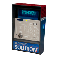
For models 9180iLQC- and 9180iDQC- (all in one cabinet)
1. Remove the outer four screws that hold the white faceplate of the control to the
cabinet or door.
2. Lift the plate up slightly and rotate out a few inches at the top as shown in the
photo above.
3. Look down between the two circuit boards and locate the 4-position DIPswitch
at the top between the front of the circuit board and the inside of the white
metal faceplate.
4. Push the switch finger that matches the desired MAXIMUM CURRENT
RANGE (chart on page B18) away from the white metal faceplate. In the photo
the #2 (50KA) switch is selected.
5. Pull the other three fingers towards the white metal faceplate.
FRONT METAL FACEPLATE WITH KEYPAD
FRONT PRINTED CIRCUIT BOARD
 Loading...