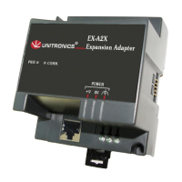
12/09 EX-A2X I/O Expansion Module Adapter, Isolated
Unitronics
5
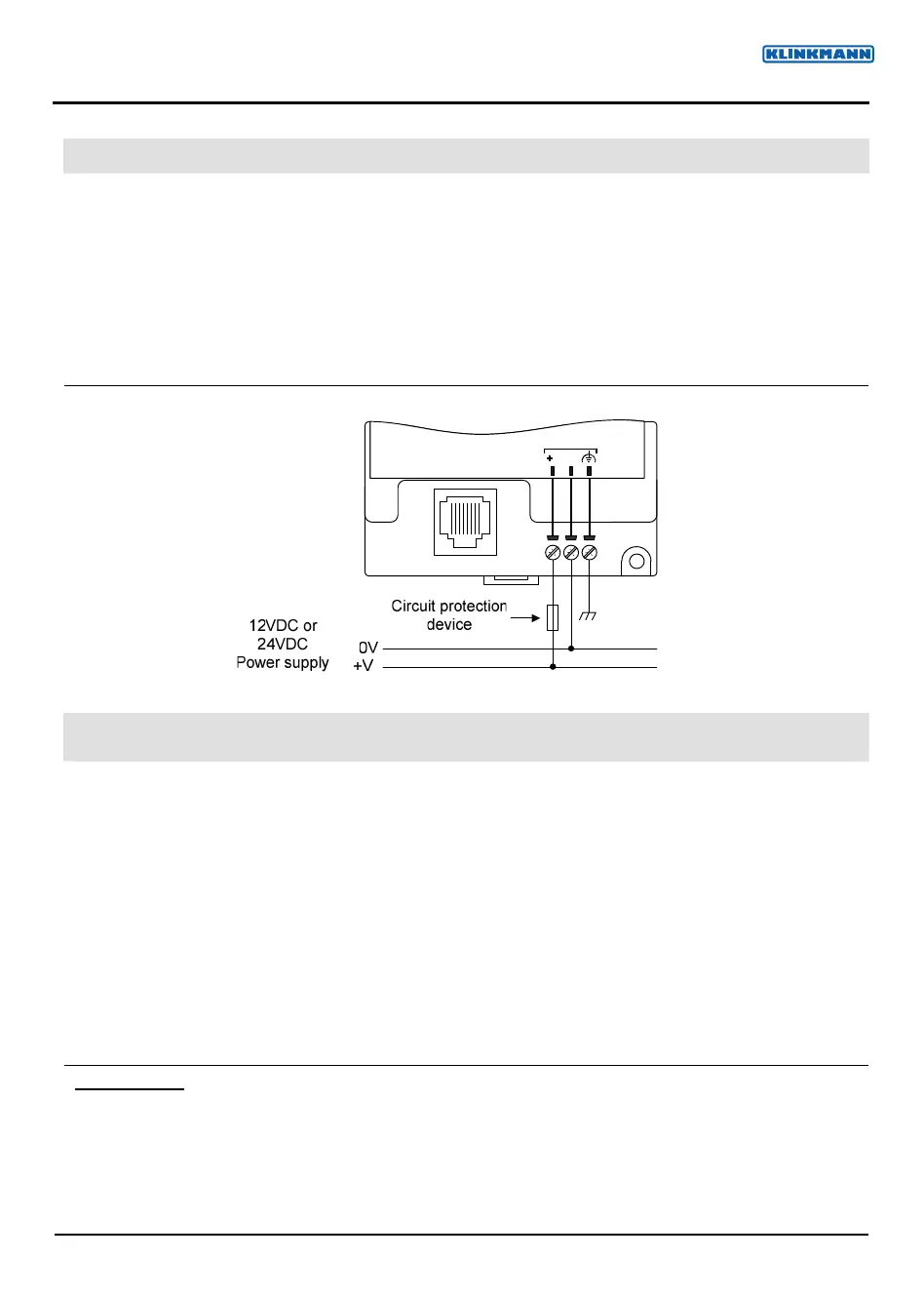
Wiring Power Supply
1. Connect the "positive" cable to the "+V" terminal, and the negative to the "0V" terminal.
Always connect the functional earth pin to the earth ground. Use a dedicated wire for this purpose; it must
not exceed 1 meter.
Do not connect the neutral or line signal of the 110/220VAC to the devices 0V pin.
In the event of voltage fluctuations or non-conformity to voltage power supply specifications, connect the
device to a regulated power supply.
A non-isolated power supply can be used provided that a 0V signal is connected to the chassis.
Note that both the OPLC and the EX-A2X must be connected to the same power supply.
The EX-A2X and the OPLC must be turned on and off simultaneously.
POWER
0V
V
EX-A2X Technical Specifications
I/O module capacity Up to 8 I/O modules can be connected to a single adapter.
Power supply 12VDC or 24VDC
Permissible range 10.2 to 28.8VDC
Max. current consumption 650mA @ 12VDC; 350mA @ 24VDC
Typical power consumption 4W
Current supply for
I/O modules
1A max. from 5V (see Note 1)
Galvanic isolation
EX-A2X power supply to:
OPLC port Yes
Expansion module port No
Status indicators
(PWR) Green LEDLit when power is supplied.
(COMM.) Green LEDLit when communication is established.
Environmental
IP20/NEMA1
Operating temperature
0° to 50° C (32 to 122°F)
Storage temperature
-20° to 60° C (-4 to 140°F)
Relative Humidity (RH) 10% to 95% (non-condensing)
Dimensions (WxHxD) 80mm x 93mm x 60mm (3.15 x 3.66 x 2.362)
Weight 125g (4.3oz.)
Mounting Either onto a 35mm DIN-rail or screw- mounted.
www.klinkmann.com
5 / 2011