EX-RC1 Remote I/O Adapter
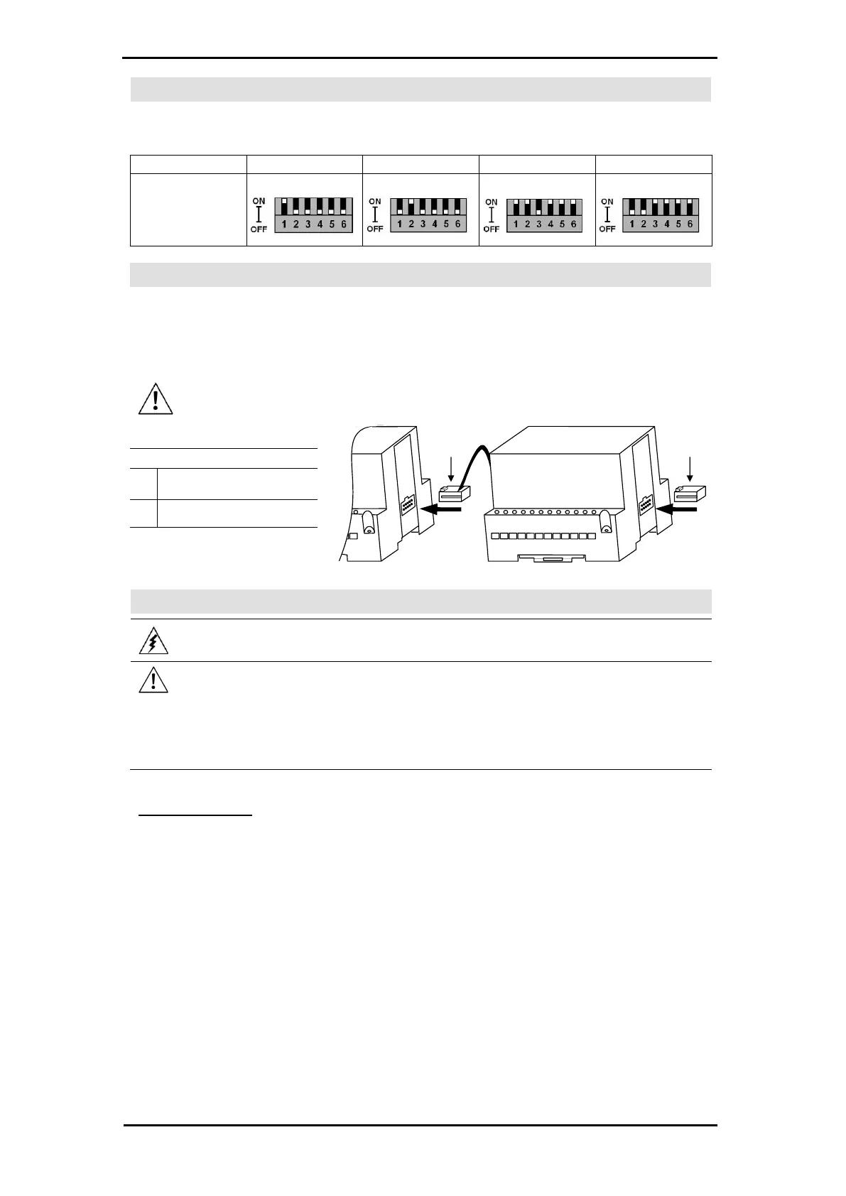
Setting the Unit ID Number
The ID number range is from 1 to 60.
The DIP switch settings represent the ID number as a binary value as shown in the following figures.
Connecting Expansion Modules
An adapter provides the interface between the OPLC and an expansion module. To connect the I/O module to
the adapter or to another module:
1. Push the module-to-module connector into the port located on the right side of the device.
Note that there is a protective cap provided with the adapter. This cap covers the port of the final
I/O module in the system.
◼ To avoid damaging the system, do not connect or disconnect the device when the
power is on.
Module-to-module
connector
◼ Do not touch live wires.
◼ Unused pins should not be connected. Ignoring this directive may damage the device.
◼ Double-check all wiring before turning on the power supply.
◼ Do not connect the ‘Neutral or ‘Line’ signal of the 110/220VAC to the device’s 0V pin.
◼ In the event of voltage fluctuations or non-conformity to voltage power supply specifications,
connect the device to a regulated power supply.
◼ Double-check all the wiring before turning on the power supply.
Use crimp terminals for wiring; use 26-14 AWG wire (0.13 mm
2
–3.31 mm
2
) for all wiring purposes.
1. Strip the wire to a length of 7±0.5mm (0.250–0.2.08 inches).
2. Unscrew the terminal to its widest position before inserting a wire.
3. Insert the wire completely into the terminal to ensure that a proper connection can be made.
4. Tighten enough to keep the wire from pulling free.
◼ To avoid damaging the wire, do not exceed a maximum torque of 0.5 N·m (5 kgf·cm).
◼ Do not use tin, solder, or any other substance on stripped wire that might cause the wire strand to break.
◼ Install at maximum distance from high-voltage cables and power equipment.
 Loading...