EasyManuals Logo

Unitronics EX-RC1 User Guide

Unitronics EX-RC1
8 pages
To Next Page IconTo Next Page
To Previous Page IconTo Previous Page
Page #7 background imageLoading...
Page #7 background image
11/22
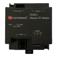
EX-RC1 Remote I/O Adapter
Unitronics
7
Communication
Connecting the EX-RC1 to a PC
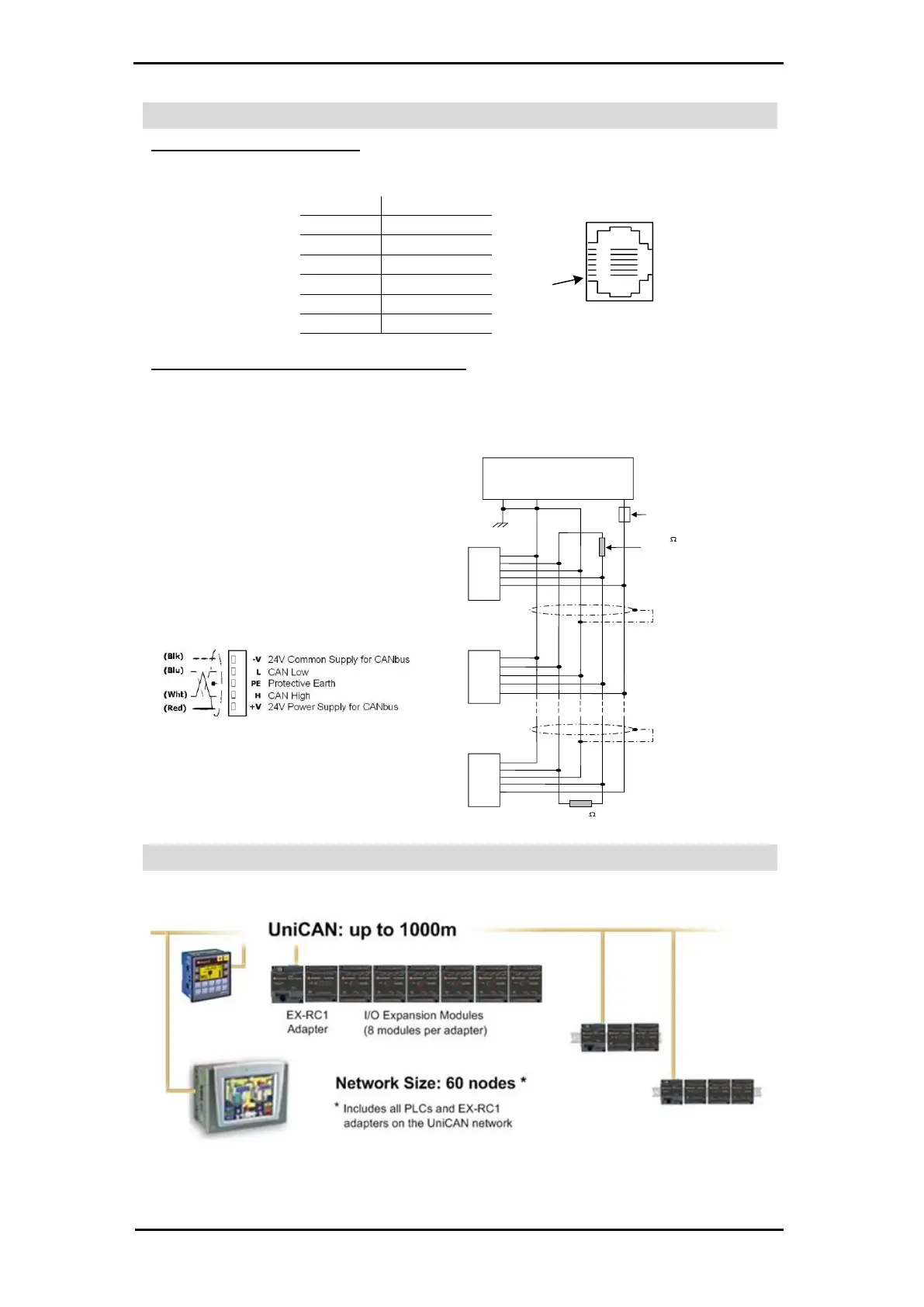
Connect the PC to the adapter via the programming cable. The pinout below shows the RS232 port signals.
Pin #
Description
Pin #1
1
2
0V reference
3
TXD signal
4
RXD signal
5
0V reference
6
Connecting the EX-RC1 to the CANbus network
Connect the EX-RC1 adapter to an OPLC as shown below. The module communicates via Unitronics’
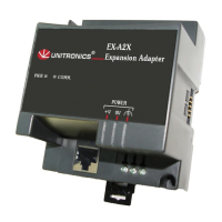
proprietary UniCAN protocol. UniCAN can comprise up to 60 nodes, including PLCs and EX-RC1
remote I/O adapters.
The CANbus port is galvanically isolated.
CANbus Wiring
121
terminating
resistor
121
terminating
resistor
Circuit
protection
device
+
-
24V Power
Supply
-V
L
H
+V
PE
-V
L
H
+V
PE
-V
L
H
+V
PE
Network terminators: Place terminators
at each end of the CANbus network.
Resistance must be set to 1%, 121Ω,
1/4W.
Connect ground signal to the earth at
only one point, near the power supply.
The network power supply need not be
at the end of the network.
CANbus Connector
Network Layout
The EX-RC1 enables you to remotely locate I/Os up to 1 kilometer from a PLC. You can include both PLCs and
adapters on the UniCAN network, up to a total of 60 nodes.

Other manuals for Unitronics EX-RC1

Questions and Answers:

Question and Answer IconNeed help?

Do you have a question about the Unitronics EX-RC1 and is the answer not in the manual?

Unitronics EX-RC1 Specifications

General IconGeneral
BrandUnitronics
ModelEX-RC1
CategoryAdapter
LanguageEnglish

Related product manuals