Do you have a question about the Unitronics Jazz JZ20-J-R16HS and is the answer not in the manual?
Key safety instructions including compliance, parameter limits, and power handling.
Avoid installation in areas with dust, gas, moisture, heat, shocks, or vibration.
Ensure 10mm space around unit edges for adequate ventilation.
Prevent water ingress and debris falling into the unit during installation.
Provides physical dimensions and mounting information for the PLC+HMI unit.
Information on add-on modules and the integral USB port for programming.
Details on DIN-rail and panel mounting, including clearance requirements.
Operate in SELV/PELV/Class 2 environments with double insulation.
Guidance on safe wiring practices, including power off, circuit breakers, and torque.
Step-by-step instructions for using crimp terminals and wire preparation.
Guidelines for separating low voltage, high voltage, and noisy lines.
Connect all system 0V points to the supply rail for proper operation.
Digital inputs arranged in groups, configurable as pnp or npn.
Details on inputs functioning as HSCs or shaft-encoders for specific models.
Information on inputs that can be wired as digital or analog (voltage/current).
Diagrams for npn (sink) and pnp (source) input wiring.
Wiring diagrams for inputs 10-15 and 16-17, npn and pnp configurations.
Wiring diagrams for inputs 10-15 and 16-17, npn and pnp configurations.
Diagrams for 2, 3, or 4-wire current analog input configurations.
Wiring diagrams for HSC inputs in npn and pnp configurations.
Wiring diagrams for shaft-encoder inputs in npn and pnp configurations.
Wiring diagrams for digital outputs on different JZ20 models.
Connect clamping diodes or RC snubber circuits for inductive loads.
Wiring diagram for voltage analog inputs (AN2-AN3).
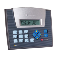
This document outlines the installation and wiring procedures for the Jazz™ PLC+HMI series, specifically the JZ20-R10/JZ20-J-R10, JZ20-R16/JZ20-J-R16, and JZ20-J-R16HS models. These devices are micro-PLCs with integrated Human Machine Interface (HMI) capabilities, designed for various industrial control applications.
The Jazz™ PLC+HMI units serve as compact programmable logic controllers with built-in display and input functionalities, allowing for direct interaction and monitoring of automated processes. The different models offer varying input and output configurations to suit diverse application needs.
All models are designed to operate within SELV/PELV/Class 2/Limited Power environments, emphasizing safety in their electrical operation. They require an external circuit breaker for protection against short-circuiting in external wiring.
The Jazz™ PLC+HMI devices offer several features designed for ease of use, flexibility, and robust operation in industrial settings.
Proper installation and adherence to guidelines contribute significantly to the longevity and reliable operation of the Jazz™ PLC+HMI units.
| Model | JZ20-J-R16HS |
|---|---|
| Humidity | 5% to 95% (non-condensing) |
| Type | Programmable Logic Controller (PLC) |
| Digital Outputs | 8 |
| Communication Ports | RS232, RS485 |
| Operating Temperature | 0°C to 50°C |
| Storage Temperature | -20°C |