© UPLIFT Desk • 1-800-349-3839 • info@upliftdesk.com • www.upliftdesk.com
4
4. ASSEMBLY INSTRUCTIONS
A.
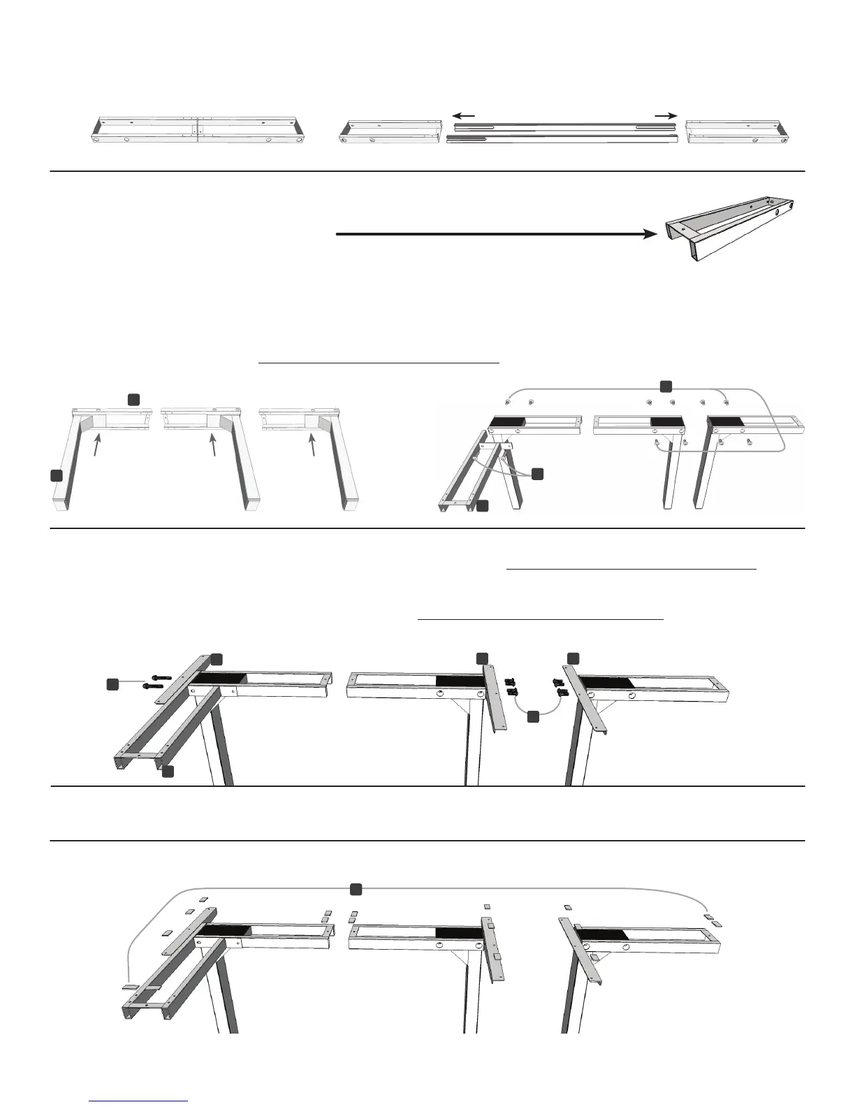
FullyseparatetheCrossbarendsfromthe2-legbox,youwillndtheCrossbarrailsinside.
g.2 g.3
PositiontheCornercrossbarend(part5)asshown(g.3).LineuptheholesoneachLegwiththeholeson
each Crossbar end. Using the supplied Allen wrench, insert ten (10) M6x14 Machine screws (part 15) into the
regular Crossbar ends, and two (2) M6x35 Machine screws (part 14) to connect the Corner crossbar end to
the regular Crossbar end, and rotate each screw only a few turns. Do not tighten fully until Step D.
C. Take the two Side brackets (part 8) and attach them to the regular leg assemblies, using four (4)
M6x14 Machine screws (part 15) each. Use the Allen wrench, and rotate each screw only a few turns.
Take the Corner bracket (part 9) and attach it to the Corner leg assembly using insert two (2) M6x35
Machine screws (part 14). Use the Allen wrench and rotate each screw only a few turns. Do not tighten
fully until Step D.
E.
Remove backing from the Adhesive pads (part 10) and position along the brackets and frames as shown.
Be sure to not cover any holes for the screws!
D. Once all of the parts are connected, you can now tighten the twelve (12) Screws from Step B
and the ten (10) Screws from Step C (22 screws in total).
B. Position the Crossbar ends (part 4) on their sides. You will be inserting
the Legs (part 1) into the Crossbar ends from below. When positioned correctly,
themounttabswillbefacingup(g.1).
Now,placetheLegs(part1)intotheCrossbarends(part4)fromthebottom(g.2).
g.1
1
4
5
5
14
14
15
15
88
9
10
 Loading...