3 s
3 s
04
T-149
T-148
T-146
10
11.1
SI0000396
X-147 T-149
T-149
T-148
T-146
T-148
T-146
11
11.3
11.5
11.2 11.2
11.4
11.4
1 2 3 4
ON DIP
T-148
T-146
T-143
T-143
T-149
T-143T-145T-149
T-148
T-146
9
9.3
9.1
9.1
9.2
9.4
9.2
Note
The general handling of thermostats in this manual is
also valid for Uponor Smatrix Base Pro X-148 Modbus
R
TU.
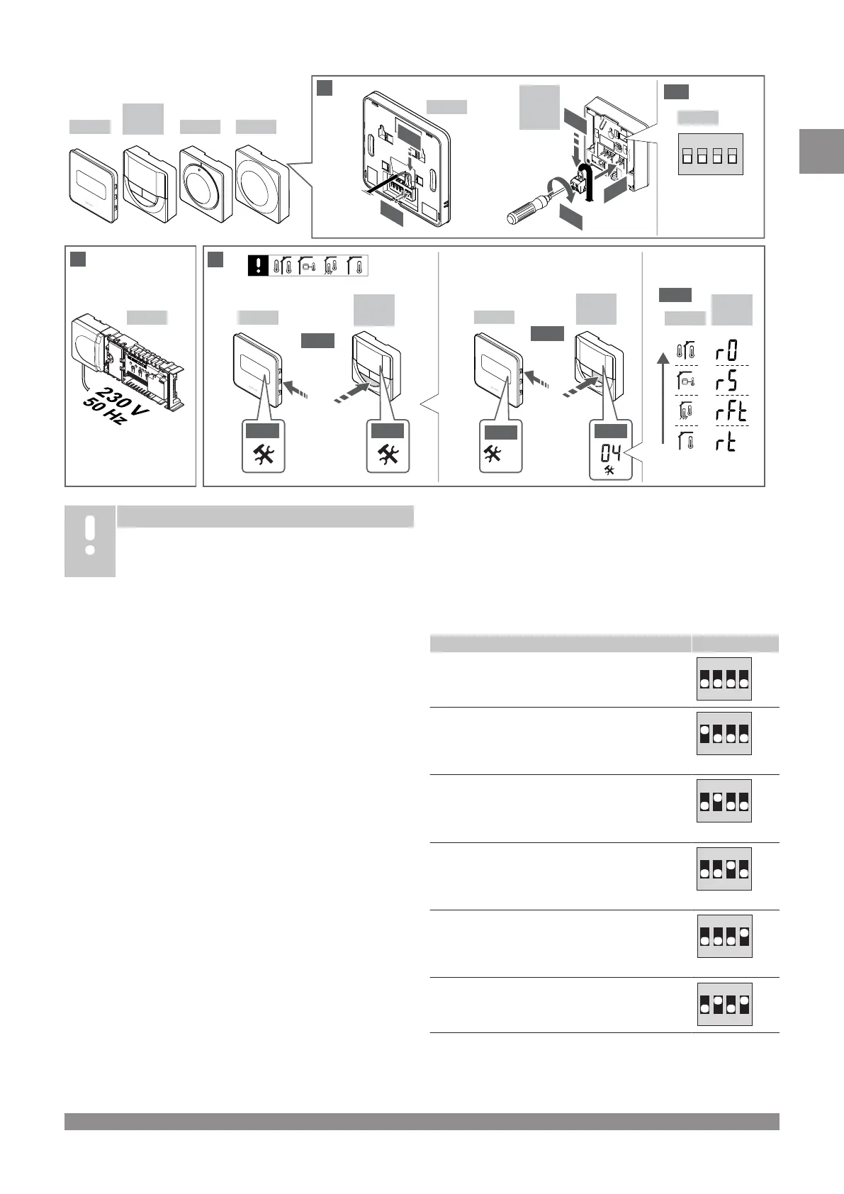
1―11 Connect the components
1. Attach the full assembly, or parts of it, to the wall either with a
DIN rail or by using wall screws and plugs.
2.
Connect the actuators.
3. Connect a thermostat communication cable to the controller,
slave module, and/or the optional star module. Note: Daisy chain
bus topology is recommended.
See section Communications protocol, Page 10 for more
information.
4. Connect a thermostat communication cable to the thermostat/
timer.
5. Connect a system bus communication cable in between
controllers and route one cable to the interface. Note: Daisy
chain bus topology is recommended.
See section Communications protocol, Page 10 for more
information.
6. Connect a system bus communication cable (6.1) and a power
cable (6.2) to the interface.
7. Check that all wiring is complete and correct:
• Actuators
• Heating/cooling switch
• Circulation pump
8. Ensure that the 230 V AC compartment of the controller is
closed and the fixing screw is tightened.
9. Connect optional external sensor (compatible thermostats only)
and set the DIP switch (public thermostat T-143 only).
Function Switch
Standard room thermostat
Standard room thermostat together with a floor
temperature sensor
Standard room thermostat, or system device, together
with an outdoor temperature sensor
System device together with a supply temperature
sensor for heating/cooling switch over function
System device where the sensor input is used for
Comfort/ECO switch over function **
Remote sensor
* The thermostat can only be registered as a system device to a
Base PRO system with multiple controllers, if it is registered to
the master controller
.
** Closed = ECO
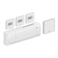
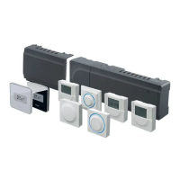
Uponor Smatrix Base PRO
|
Quick guide
|
7
EN