EasyManua.ls Logo

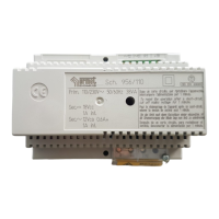
urmet domus 9006/1 User Manual

urmet domus 9006/1
24 pages
To Next Page IconTo Next Page
Page #1 background imageLoading...
Page #1 background image
INSTRUCTIONS FOR URMET DOMUS DEVICE INTERCHANGEABILITYBASIC SYSTEM DIAGRAMS
sec.1f
−−−−
1
DOOR PHONE - VIDEO DOOR PHONE SYSTEMS: Installation Diagrams
INSTRUCTIONS FOR
URMET DOMUS DEVICE
INTERCHANGEABILITY
SECTION 1F
(REV.B)
Download from:
www.urmetdomus.com
Technical Manuals area
Question and Answer IconNeed help?

Do you have a question about the urmet domus 9006/1 and is the answer not in the manual?

urmet domus 9006/1 Specifications

General IconGeneral
Brandurmet domus
Model9006/1
CategoryIntercom System
LanguageEnglish

Summary

Replacing Relay Power Unit 786/5A and 9006/5 with 786/15

Electronic Call Systems Wiring Diagrams

Wiring diagrams for electronic call systems with and without buzzers.

Traditional Call Systems Wiring Diagrams

Wiring diagrams for traditional call systems with buzzers.

Replacing Video Door Phone Power Unit 789 with 789/1A

789/1A Terminal Correspondence

Table detailing terminal correspondence between 789 and 789/1A power units.

Replacing Video Door Phone Power Unit 789 and 789/1A with 789/5B

789/5B Characteristics and Wiring

Details on 789/5B suitability and wiring for replacing 789/789/1A.

Replacing Door Phone Power Unit 1840/22 with 1090/850

1090/850 Terminal Correspondence

Table detailing terminal correspondence between 1840/22 and 1090/850 power units.

Replacing Door Phone Power Unit 787/4 with 786/4

786/4 Terminal Correspondence

Table detailing terminal correspondence between 787/4 and 786/4 power units.

Replacing Door Phone Two-Channel Power Unit 4340/20 with 752/20

752/20 Terminal Correspondence & Wiring

Diagram showing terminal correspondence for 4340/20 and 752/20 power units.

Replacing Two-Channel Apartment Station 4340/23 with 752/23

752/23 Terminal Correspondence & Wiring

Diagram showing terminal correspondence for 4340/23 and 752/23 apartment stations.

Replacing Video Door Phone Power Unit 7073, 7073/1, 7073/2 with 789/1A

789/1A Compatibility and Wiring

Details compatibility exceptions and wiring for 7073 series replacement with 789/1A.

Replacing Video Door Phone Power Unit 7073 Series with 789/1A (Scout Systems)

Scout and Camera Systems Wiring

Wiring diagram for Scout and Camera systems using 789/1A.

Replacing Video Door Phone Power Unit 7073 Series with 789/1A (Sentinel Systems)

Sentinel, Explorer, Ranger Wiring

Wiring diagram for Sentinel, Explorer, Ranger systems using 789/1A.

Replacing Video Door Phone Power Unit 7073 Series with 789/1A (Switchboard Systems)

CCD Camera Systems Wiring

Wiring for CCD camera systems with switchboard using 789/1A.

Replacing Video Door Phone Power Unit 7073 Series with 789/1A (Vidicon Systems)

Replacing Door Phone Power Units 9006/1, 9006/2, 9006/14, 9006/22 with 786/11

Replacing Switchboard Power Unit 9006/3 with 786/3A

Replacing Door Phone Power Unit 9008/14 with 786/38A

Replacing Door Unit 5150/500 with 1128/500

Replacing Relay Boxes 788/21, 788/11, 4340/11, 4520/10 with 788/52

Replacing Relay Boxes 9332/1, 4330/31, 788/1 with 788/51

Replacing Supplementary Video Power Unit 7073/5A with 789/2

Replacing Relay Box 9332/5 and 788/5 with 788/52

Replacing Relay Box 9330 (II Series) and 788/30 with 788/52

Replacing Relay Box 9332/8 and 788/8 with 788/58

Replacing 12VAC Transformer 9000/20 with 9000/230

Replacing Relay Box 788/4 with 788/54

Replacing Door Phone Power Unit 786/1 with 786/11

Replacing Door Phone Power Unit 786/14 with 786/11

Related product manuals