RECOMMENDED LOCATION OF ALARMS
/RFDWHWKH¿UVWVPRNHDODUPLQWKHLPPHGLDWHDUHDRIWKHEHGURRPV7U\WRSURWHFWWKHHVFDSH
route as the bedrooms are usually farthest from an exit. If more than one sleeping area exists,
locate additional smoke alarms in each sleeping area. If a hall is more than 40 feet (12 meters)
long, install a smoke alarm at each end.
/RFDWHDGGLWLRQDOVPRNHDODUPVWRSURWHFWDQ\VWDLUZD\DVVWDLUZD\VDFWOLNHFKLPQH\VIRUVPRNH
and heat.
/RFDWHDWOHDVWRQHVPRNHDODUPRQHYHU\ÀRRUOHYHO
/RFDWHDVPRNHDODUPLQDQ\DUHDZKHUHDVPRNHUVOHHSVRUZKHUHHOHFWULFDODSSOLDQFHVDUH
operated in sleeping areas.
• Smoke, heat and other combustion products rise to the ceiling and spread horizontally. Mounting
the smoke alarm on the ceiling in the center of the room places it closest to all points in the room.
&HLOLQJPRXQWLQJLVSUHIHUUHGLQRUGLQDU\UHVLGHQWLDOFRQVWUXFWLRQ+RZHYHULQPRELOHKRPHVZDOO
mounting on an inside partition is preferred to avoid the thermal barrier that may form at the ceiling.
:KHQPRXQWLQJVPRNHDODUPRQWKHFHLOLQJORFDWHLWDPLQLPXPRIFPIURPDVLGHZDOO
or corner (see Diagram A).
:KHQPRXQWLQJVPRNHDODUPRQDZDOOLIORFDOFRGHVDOORZXVHDQLQVLGHZDOOZLWKWKHWRSHGJH
RIWKHVPRNHDODUPDPLQLPXPRIFPDQGDPD[LPXPRIFPEHORZWKHFHLOLQJ
ZDOOLQWHUVHFWLRQV6HH'LDJUDP$
Page 3
Sloped Ceilings (Peaked Ceilings):
Smoke alarms or smoke detectors mounted on a peaked ceiling shall be located within 36 in. (914 mm)
horizontally of the peak, but not closer than 4 in. (102 mm) vertically to the peak.
Sloped Ceilings (Shed Ceilings):
Smoke alarms or smoke detectors mounted on a sloped ceiling having a rise greater than 1 ft. in 8 ft. (1
m in 8 m) horizontally shall be located within 36 in. (914 mm) of the high side of the ceiling, but not closer
than 4 in. (102 mm) from the adjoining wall surface.
Tray-Shaped Ceilings:
Smoke Alarms or smoke detectors shall be installed on the highest portion of the ceiling or on the sloped
portion of the ceiling within 12 in. (305 mm) vertically down from the highest point.
Mobile Home Installation:
For minimum protection, smoke alarms should be installed in compliance with H.U.D. Manufactured
Home Construction Safety Standards, Title 24 CFR, Section 3280.208 and Section 3282. For additional
protection, see Single Story Residence smoke alarm requirements/recommendations for Existing Homes
and New Construction Homes.
Note: For mobile homes built before 1978, install smoke alarms on inside walls between 4” and 12” from
the ceiling (older mobile homes have little or no insulation in the ceiling). This is especially important if
the ceiling is unusually hot or cold.
Install a smoke alarm inside each bedroom and in the hallway outside each separate sleeping area.
Existing Homes:
The NFPA requires a smoke alarm on every level and outside each sleeping area in existing construction.
An existing household with one level and one sleeping area is required to have one smoke alarm.
New Construction Homes and Manufactured Homes:
The NFPA requires AC-powered, interconnected smoke alarms to be installed inside each bedroom, outside
each bedroom area, and on every level of the home. They also require a minimum of two AC-powered,
interconnected smoke alarms in any new construction home.
THIS SMOKE ALARM WILL NOT WORK WITHOUT 120 VAC POWER AND A
GOOD BATTERY PROPERLY INSTALLED. THE SMOKE ALARM SHOULD BE
TESTED WHEN INSTALLED AND THEN TESTED WEEKLY AFTER THAT.
INSTALLATION INSTRUCTIONS: CAUTION!! READ CAREFULLY.
Installation of this alarm must conform to the electrical codes in your area; Article 760 of
the National Electrical Code, NFPA 72, 101; SBC (SBCCI); UBC (ICBO); NBC (BOCA): OTFDC
(CABO), and any other local or building codes that may apply. Wiring and installation must
be performed by a licensed electrician. Failure to follow these guidelines may result in
injury or property damage.
This alarm must be powered by a 24-hour, 120V AC 60Hz circuit. Be sure the circuit cannot
be turned off by a switch, dimmer or ground fault circuit interrupter. Failure to connect this
alarm to a 24-hour circuit may prevent it from providing constant protection.
IMPORTANT: Do not subject this smoke alarm to megger, high voltage or high-pot tests.
Remove the smoke alarm(s) before high-potting tests occur on the circuit or system.
(Ref. Section 550-17, National Electrical Code, 2002 Edition).
ELECTRICAL SHOCK HAZARD
Turn off power to the area where you will install this alarm at the circuit breaker or fuse box
before beginning installation. Failure to turn off the power before installation may result in
serious electrical shock, injury or death.
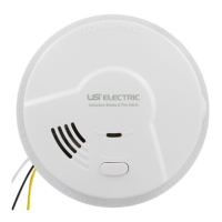
CAUTION: THIS SMOKE ALARM IS SEALED. THE COVER IS NOT REMOVABLE!
• A mounting bracket is provided on the back of the alarm.
• Remove the mounting bracket from the back of the alarm by holding the mounting bracket and
WZLVWLQJWKHDODUPLQWKHGLUHFWLRQLQGLFDWHGE\WKH7:,67725(029(DUURZRQWKHVLGHRI
the alarm base.
OPTIONAL TAMPER RESISTANT FEATURES:7KHUHDUHWZRVHSDUDWHWDPSHUUHVLVWDQWORFNLQJ
features provided for this model. Activating one or both of these features deters someone from
removing the smoke alarm from the mounting bracket or removing the battery from the alarm. The
EUHDNDZD\ORFNLQJSLQVDUHFOHDUO\PDUNHGDQGPROGHGLQWRWKHPRXQWLQJEUDFNHW5HIHUWRWKH
diagram on the next page.
TO ACTIVATE THE LOCKING FEATURES: Do not activate the locking features until you have
activated the battery, mounted the smoke alarm to the bracket and tested the smoke alarm. Refer
to OPERATION, TESTING & MAINTENANCE instructions on Page 6.
'HWDFKWKHEUHDNDZD\DODUPORFNLQJSLQIURPWKHPRXQWLQJEUDFNHW
AVOID THESE LOCATIONS
WKHJDUDJH±SURGXFWVRIFRPEXVWLRQDUHSURGXFHGZKHQ\RXVWDUW\RXUYHKLFOH
QHDUDSSOLDQFHVRUDUHDVZKHUHQRUPDOFRPEXVWLRQUHJXODUO\RFFXUVNLWFKHQVQHDUIXUQDFHV
JDVKRWZDWHUKHDWHUV8VHVPRNHDODUPVZLWKSKRWRHOHFWULFVHQVRUVRUVPRNHDODUPVZLWK
Silence Feature for these areas.
LQDUHDVZLWKKLJKKXPLGLW\OLNHEDWKURRPVRUDUHDVQHDUGLVKZDVKHUVRUZDVKLQJPDFKLQHV
,QVWDOODWOHDVWIHHWPHWHUVDZD\IURPWKHVHDUHDV
• in areas of turbulent air such as air returns or heating and cooling supply vents, smoke alarms
VKDOOQRWEHORFDWHGZKHUHDLUÀRZSUHYHQWVVPRNHIURPUHDFKLQJWKHDODUPV
LQH[WUHPHO\GXVW\GLUW\RULQVHFWLQIHVWHGDUHDV/RRVHSDUWLFOHVLQWHUIHUHZLWKVPRNHDODUPRSHUDWLRQ
LQDUHDVZKHUHWHPSHUDWXUHPD\IDOOEHORZ
0
F (4.4
0
C) or rise above 100
0
F (37.8
0
C).
FORVHUWKDQIRRWPIURPÀXRUHVFHQWOLJKWVHOHFWULFDOQRLVHDQGÀLFNHULQJPD\DIIHFWWKH
DODUPVRSHUDWLRQ
• closer than 3 feet (0.9m) horizontal path from the tip of the blade of a ceiling suspended (paddle) fan.
RQDSRRUO\LQVXODWHGFHLOLQJRUH[WHULRUZDOOPRXQWVPRNHDODUPRQDQLQVLGHZDOO
Page 4
(DUO\ZDUQLQJ¿UHGHWHFWLRQLVEHVWDFKLHYHGE\WKHLQVWDOODWLRQRI¿UHGHWHFWLRQHTXLSPHQW
in all rooms and areas of the household as follows: A smoke alarm installed in each separate
sleeping area (in the vicinity of, but outside of, the bedrooms); and, as appropriate, heat
or smoke alarms in living rooms, dining rooms, kitchens, hallways, attics, furnace rooms,
closets, utility storage rooms, basements and attached garages. Test the alarms weekly to
assure proper operation.
DO NOT TAMPER WITH WIRES WHEN POWER IS ON!
For alarms that are used as single smoke alarms, do not connect the yellow wire to anything.
Insulate this wire (tape it) in place to make certain the yellow wire cannot contact any metal
parts.
,QWHUFRQQHFWHGDODUPVFDQSURYLGHHDUOLHUZDUQLQJRI¿UHWKDQVWDQGDORQHDODUPVHVSHFLDOO\
LID¿UHVWDUWVLQDUHPRWHDUHDRIWKHGZHOOLQJ:KHQDODUPVDUHLQWHUFRQQHFWHGDOODODUPV
ZLOOVRXQGZKHQRQHDODUP¿UVWJRHVLQWRDODUP7KLVDODUPPD\EHLQWHUFRQQHFWHGZLWKD
total of not more than 24 interconnected devices, i.e., as many as 11 other USI ELECTRIC
or UNIVERSAL model smoke alarms or combination smoke and carbon monoxide (CO) or
smoke and carbon monoxide / natural gas alarms; 6 other initiating alarms which may be
a combination of USI ELECTRIC or UNIVERSAL CO Alarms and Heat Alarms; and six other
non-initiating devices such as USI ELECTRIC Relay Modules.
This alarm can be interconnected with the following models: MI106S, MIC1509S, MDSCN111,
MICN109, MCN108, USI-1103, USI-1203, USI-1204, USI-1208 (Part #USI-1209), USI-1213, USI-
5204, USI-3204, SS-785, SS-790, SS-795, SS-2795, SS-2895, USI-7385, USI-7390, USI-7485,
USI-7490, CD-9385, CD-9390, CD-9485, CD-9490, CD-9795, USI-7795, 5304, MI106, MDS107,
3885, 3895, MP118, MP117, USI-2430, USI-960.
When any one of these interconnected models alarms it will trigger the corresponding alarm
within the interconnected system with respect to their sensing capabilities. Natural gas
detection is only present in models MDSCN111, MICN109, MDSCN103, MICN102, MCN105,
and MCN108, therefore a natural gas alarm will NOT trigger the alarm of non- natural gas
sensing models within an interconnected system.
The following alarms cannot reset units on an interconnected system: USI-7795, CD-9795,
USI-7385, USI-7390, USI-7485, USI-7490, CD-9385, CD-9390, CD-9485, CD-9490.
The following alarms cannot trigger Quick Find
®
Alarm Origination on an interconnected
system: USI-7385, USI-7390, USI-7485, USI-7490, CD-9385, CD-9390, CD-9485, CD-9490.
The following alarms can trigger Quick Find
®
Alarm Origination, but will not indicate Alarm
Origination on an interconnected system: USI-1103, USI-1203, USI-1204, USI-1208 (Part
#USI-1209), USI-1213, USI-5204, USI-5208, USI-5213, USI-3204, CD-9795, USI-7795, USI-2430,
SS-785, SS-790, SS-795, SS-2795, SS-2790, SS-2785, SS-2895, HD-130.
,QVHUWWKHSLQLQWRWKHKROHIRUWKHIHDWXUH\RXDUHDFWLYDWLQJ5HIHUWRWKHGLDJUDPEHORZIRU
correct placement.
TO DEACTIVATE THE LOCKING FEATURES: To remove the smoke alarm for cleaning or servicing
RUWRUHSODFHWKHEDWWHU\\RXPXVW¿UVWUHPRYHWKHDSSURSULDWHORFNLQJSLQLILWKDVEHHQLQVWDOOHG
7XUQRII$&SRZHUWRWKHFLUFXLW
2. Use long nose pliers to pull the locking pin out of the hole.
,WLVQRZSRVVLEOHWRUHPRYHWKHVPRNHDODUPRUUHSODFHWKHEDWWHU\
WIRING INSTRUCTIONS:
D 7KH DSSURSULDWH SRZHU VXSSO\ LV 9ROW VLQJOH SKDVH SRZHU VXSSOLHG IURP D QRQ
VZLWFKDEOHFLUFXLW127SURWHFWHGE\DJURXQGIDXOWFLUFXLWLQWHUUXSWHU
E 7XUQRII$&SRZHUWRWKHFLUFXLWEHIRUHZLULQJWKHVPRNHDODUP
F 7KHUH DUH WKUHH SLJWDLO ZLUHV EODFN ZKLWH DQG \HOORZ FRPLQJ IURP WKH$& QUICK
CONNECTOR7KHSURSHUZLUHFRQQHFWLRQLVDVIROORZV
WIRES FROM QUICK CONNECTOR CONNECT TO
BLACK "HOT" side of AC line
WHITE "NEUTRAL" side of AC line
<(//2: ,QWHUFRQQHFWZLUHVRIRWKHUVPRNHDODUPV
INSERT ALARM
LOCKING PIN HERE
ALARM/BRACKET
LOCKING PIN
BATTERY LOCKING PIN
INSERT BATTERY
LOCKING PIN HERE
Page 5
 Loading...