DO NOT TAMPER WITH WIRES WHEN POWER IS ON!
For alarms that are used as single smoke alarms, do not connect the yellow wire to anything.
Insulate this wire (tape it) in place to make certain the yellow wire cannot contact any metal
parts.
,QWHUFRQQHFWHGDODUPVFDQSURYLGHHDUOLHUZDUQLQJRI¿UHWKDQVWDQGDORQHDODUPVHVSHFLDOO\
LID¿UHVWDUWVLQDUHPRWHDUHDRIWKHGZHOOLQJ:KHQDODUPVDUHLQWHUFRQQHFWHGDOODODUPV
ZLOOVRXQGZKHQRQHDODUP¿UVWJRHVLQWRDODUP7KLVDODUPPD\EHLQWHUFRQQHFWHGZLWKD
total of not more than 24 interconnected devices, i.e., as many as 11 other USI ELECTRIC
or UNIVERSAL model smoke alarms or combination smoke and carbon monoxide (CO) or
smoke and carbon monoxide / natural gas alarms; 6 other initiating alarms which may be
a combination of USI ELECTRIC or UNIVERSAL CO Alarms and Heat Alarms; and six other
non-initiating devices such as USI ELECTRIC Relay Modules.
This alarm can be interconnected with the following models: MI106S, MIC1509S, MDSCN111,
MICN109, MCN108, USI-1103, USI-1203, USI-1204, USI-1208 (Part #USI-1209), USI-1213, USI-
5204, USI-3204, SS-785, SS-790, SS-795, SS-2795, SS-2895, USI-7385, USI-7390, USI-7485,
USI-7490, CD-9385, CD-9390, CD-9485, CD-9490, CD-9795, USI-7795, 5304, MI106, MDS107,
3885, 3895, MP118, MP117, USI-2430, USI-960.
When any one of these interconnected models alarms it will trigger the corresponding alarm
within the interconnected system with respect to their sensing capabilities. Natural gas
detection is only present in models MDSCN111, MICN109, MDSCN103, MICN102, MCN105,
and MCN108, therefore a natural gas alarm will NOT trigger the alarm of non- natural gas
sensing models within an interconnected system.
The following alarms cannot reset units on an interconnected system: USI-7795, CD-9795,
USI-7385, USI-7390, USI-7485, USI-7490, CD-9385, CD-9390, CD-9485, CD-9490.
The following alarms cannot trigger Quick Find
®
Alarm Origination on an interconnected
system: USI-7385, USI-7390, USI-7485, USI-7490, CD-9385, CD-9390, CD-9485, CD-9490.
The following alarms can trigger Quick Find
®
Alarm Origination, but will not indicate Alarm
Origination on an interconnected system: USI-1103, USI-1203, USI-1204, USI-1208 (Part
#USI-1209), USI-1213, USI-5204, USI-5208, USI-5213, USI-3204, CD-9795, USI-7795, USI-2430,
SS-785, SS-790, SS-795, SS-2795, SS-2790, SS-2785, SS-2895, HD-130.
,QVHUWWKHSLQLQWRWKHKROHIRUWKHIHDWXUH\RXDUHDFWLYDWLQJ5HIHUWRWKHGLDJUDPEHORZIRU
correct placement.
TO DEACTIVATE THE LOCKING FEATURES: To remove the smoke alarm for cleaning or servicing
RUWRUHSODFHWKHEDWWHU\\RXPXVW¿UVWUHPRYHWKHDSSURSULDWHORFNLQJSLQLILWKDVEHHQLQVWDOOHG
7XUQRII$&SRZHUWRWKHFLUFXLW
2. Use long nose pliers to pull the locking pin out of the hole.
,WLVQRZSRVVLEOHWRUHPRYHWKHVPRNHDODUPRUUHSODFHWKHEDWWHU\
WIRING INSTRUCTIONS:
D 7KH DSSURSULDWH SRZHU VXSSO\ LV 9ROW VLQJOH SKDVH SRZHU VXSSOLHG IURP D QRQ
VZLWFKDEOHFLUFXLW127SURWHFWHGE\DJURXQGIDXOWFLUFXLWLQWHUUXSWHU
E 7XUQRII$&SRZHUWRWKHFLUFXLWEHIRUHZLULQJWKHVPRNHDODUP
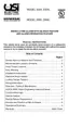
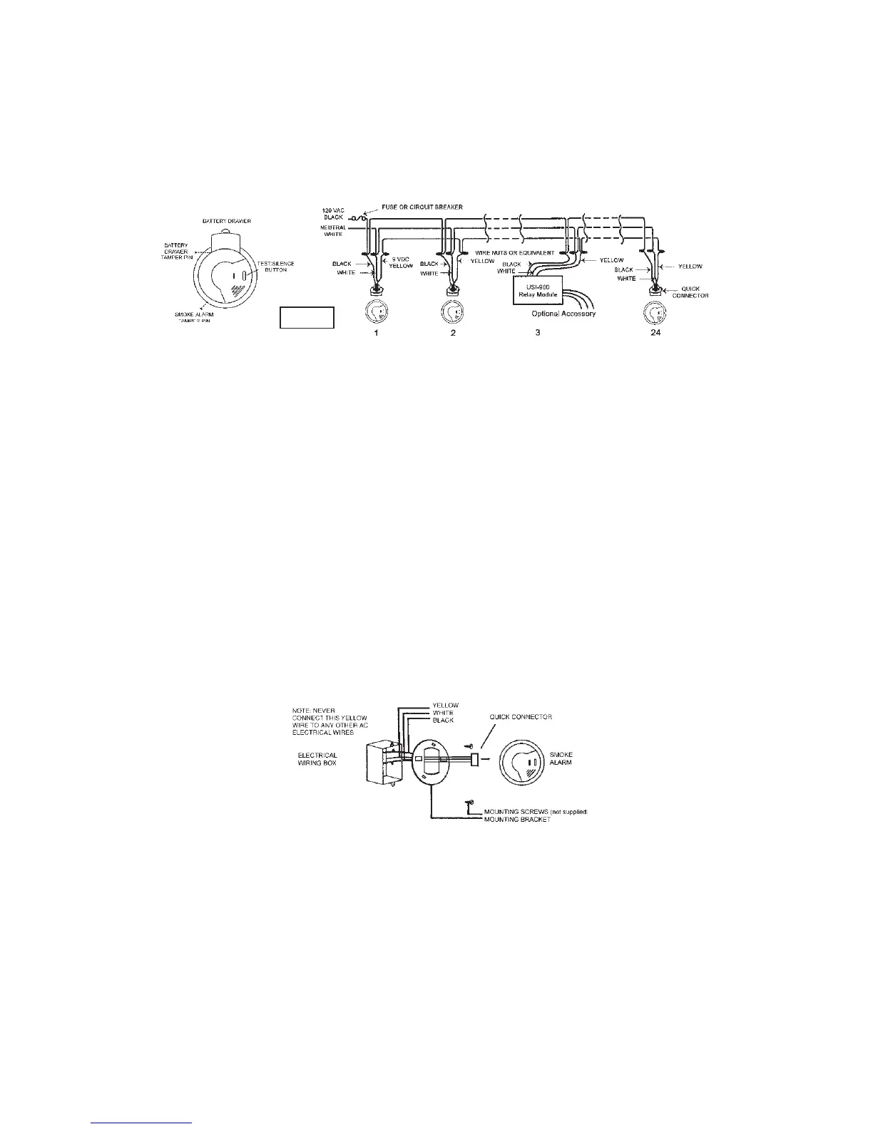
F 7KHUH DUH WKUHH SLJWDLO ZLUHV EODFN ZKLWH DQG \HOORZ FRPLQJ IURP WKH$& QUICK
CONNECTOR7KHSURSHUZLUHFRQQHFWLRQLVDVIROORZV
WIRES FROM QUICK CONNECTOR CONNECT TO
BLACK "HOT" side of AC line
WHITE "NEUTRAL" side of AC line
<(//2: ,QWHUFRQQHFWZLUHVRIRWKHUVPRNHDODUPV
INSERT ALARM
LOCKING PIN HERE
ALARM/BRACKET
LOCKING PIN
BATTERY LOCKING PIN
INSERT BATTERY
LOCKING PIN HERE
Page 5
OPERATION, TESTING & MAINTENANCE
OPERATION:7KHVPRNHDODUPLVRSHUDWLQJRQFHWKH$&SRZHULVFRQQHFWHGDQGWXUQHGRQWKH
battery must also be installed). When products of combustion are sensed, the alarm sounds a loud
DODUPZKLFKFRQWLQXHVXQWLOWKHDLULVFOHDUHG
This alarm incorporates the NFPA recognized horn signal for evacuation. During alarm mode, the
KRUQSURGXFHVWKUHHEHHSVIROORZHGE\DWZRVHFRQGSDXVHDQGWKHQFRQWLQXDOO\UHSHDWV
READY/ACTIVE CONDITION:7KHUHG/('EOLQNVRQRQFHDSSUR[HYHU\VHFRQGVWRLQGLFDWH
the alarm is properly functioning.
LOCAL ORIGINATING ALARM CONDITION: The red LED blinks on approx. every 2 seconds and
the alarm emits a loud, pulsating alarm sound.
NON-ORIGINATING ALARM CONDITION: The red LED is off and the alarm emits a loud, pulsating
alarm.
GREEN LED:7KHJUHHQ/('LVRQZKHQHYHU$&SRZHULVWXUQHGRQ
The following alarms cannot be reset through an interconnected system: USI-1103, USI-1203,
USI-1204, USI-1208 (Part #USI-1209), USI-1213, USI-3204, USI-2430, SS-785, SS-790, SS-795,
SS-2795, SS-2895, USI-7385, USI-7390, USI-7485, USI-7490, CD-9385, CD-9390, CD-9485,
CD-9490, CD-9795, USI-7795.
Interconnected CO alarms or CO alarm circuit of combination smoke and CO alarms will only
respond if a CO alarm / event initiates the alarm. All other alarms remain silent.
Interconnected smoke alarms, heat alarms and relay modules will only respond if a smoke
alarm / event or heat alarm / event initiates the alarm. All CO alarms remain silent.
Note that smoke alarms without battery backup will not respond during an AC power failure.
NOTE: Relay Modules/USI-960 will not respond if a CO alarm / event initiates the alarm.
The yellow wire is used only for multiple station operations with USI ELECTRIC or UNIVERSAL
Model alarms only. Connecting this yellow wire to any other circuits may result in damage
and alarm malfunction. When alarms are interconnected, all alarms must be powered from
a single AC branch circuit. If local codes do not permit, be sure the neutral wire is common
WRERWKSKDVHV7KHPD[LPXPZLUHUXQGLVWDQFHEHWZHHQWKH¿UVWDQGODVWDODUPGHYLFH
in an interconnected system is 1,000 feet. NOTE: Use standard household wire (18 gauge
RUODUJHUUDWHGDWOHDVW9DVUHTXLUHGE\ORFDOFRGHVDYDLODEOHDWDOOHOHFWULFDOVXSSO\
hardware stores.
The wiring to be used shall be in accordance with the provisions of Articles 210 and
300.3(B) of the National Electrical Code, ANSI/NFPA 70. In addition, the resistance of the
interconnecting wiring shall be a maximum of 10 Ohms.
2. Attach the mounting bracket to the electrical junction box.
3. To activate 9 volt battery and alarm, hold the QUICK DRAW
(R)
EDWWHU\GUDZHUFORVHGSXOODQG
UHPRYH WKH 38//7$% &RQ¿UP WKDW WKH HQWLUH 38//7$% KDV EHHQ FRPSOHWHO\ UHPRYHG
'LVFDUG38//7$%
3OXJWKH$&48,&.&211(&725LQWRWKHDODUPEDVH3XVKDQGWZLVWWKHDODUPFORFNZLVH
onto the mounting bracket.
5. See "OPTIONAL TAMPER RESISTANT FEATURES" and "TO ACTIVATE THE LOCKING
FEATURES" instructions on Page 4.
7XUQRQ$&SRZHUDQGFKHFNWKH/('VIRUSURSHURSHUDWLRQ7KHJUHHQ/('VKRXOGEHRQWR
LQGLFDWH$&SRZHU7KHUHG/('EOLQNVRQRQFHDSSUR[HYHU\VHFRQGVWRLQGLFDWHSURSHU
operation.
Page 6
120 VAC 60Hz
100mA Max.
 Loading...