4 / 32 P/N 1070346 • REV 5.0 • ISS 03OCT11
Note: The TERM jumper (terminator) can be placed on the last
device on the bus.
Wiring specifications
The ATS1235 can be located up to 1500 m from the ATS
control panel using a WCAT52/54 cable. This cable has a core
with a gauge of 24 AWG, the diameter is 0.52 mm and the
area is 0.22 mm².
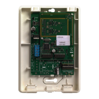
Addressing ATS1235
Each wireless DGP connected to the ATS control panel bus
must identify itself to the ATS control panel with a unique
address set with the DIP switches 5 to 8 on the DGP. Table 1
below shows 15 possible wireless DGP addresses.
Table 1: Address DIP switch settings
Address Setting Address Setting
1 1000 9 1001
2 0100 10 0101
3 1100 11 1101
4 0010 12 0011
5 1010 13 1011
6 0110 14 0111
7 1110 15 1111
8 0001
See examples in Figure 4.
Note: Do not use address 0. This is reserved for factory
testing.
DIP switches 1 to 4 are not used.
Closing the ATS1235 housing
1. Replace the plastic cover.
2. Mount sensors and 868 MHz AM repeater as required.
A repeater can be added later if sensor performance or
signal strength is found to be inadequate.
Powering up the ATS1235
1. Before powering up the panel and receiver module, verify
that all wiring at the panel and ATS1235 wireless receiver
is correct.
2. Connect the panel backup battery and AC power.
Output numbering
The output numbering of a wireless DGP is in line with all
DGPs (refer to Table 2 below), but the wireless DGP has no
ph
ysical outputs or output expansion available. However, any
available output can be programmed in the range of 1 to 255
via key fob programming in Menu 6.
Note: Remember that in standard DGP mode the first relay of
each DGP (relay 17 for DGP 1) can be used to mask
supervision on sensors by using time zones to energise/de-
energise the virtual relay (see “Menu 11, Supervision Options”
on page 7).
Table 2: Output numbering
Control panel 1–16 DGP 8 129–144
DGP 1 17–32 DGP 9 145–160
DGP 2 33–48 DGP 10 161–176
DGP 3 49–64 DGP 11 177–192
DGP 4 65–80 DGP 12 193–208
DGP 5 81–96 DGP 13 209–224
DGP 6 97–112 DGP 14 225–240
DGP 7 113–128 DGP 15 241–255
Zone numbering
The wireless DGP zone database can be set up for either 16 or
32 zones. (32 zones only applicable for Advisor Master) This
means you can add up to 16 or up to 32 wireless devices to
the DGP. If DGP 1 has been programmed with 32 zones, then
the next 16 zones (33 to 48) normally belonging to DGP 2 will
now belong to DGP 1 and the RAS display will show 17 to 48
(for details, refer to Table 3 below, and to “Menu 13, DGP
Settings” on page 7).
Table 3: Zone numbering
Control panel 1–16 DGP 8 129–144
DGP 1 17–32 DGP 9 145–160
DGP 2 33–48 DGP 10 161–176
DGP 3 49–64 DGP 11 177–192
DGP 4 65–80 DGP 12 193–208
DGP 5 81–96 DGP 13 209–224
DGP 6 97–112 DGP 14 225–240
DGP 7 113–128 DGP 15 241–255
Introduction to programming
See Figure 5.
Each sensor must be programmed into the wireless DGP
database via an ATS control panel RAS keypad. In this
procedure it is assumed that:
• Sensor / key fob documentation is available or known.
• The DIP switch address for the wireless DGP is set
correctly.
• Sensors are physically installed or mounted.
• The repeater has been installed and programmed if
required.
The specific details for each sensor need to be reviewed on
the related component sheet. In general, you need to know
that the sensor can be “learned” by the system by activating it,
for example, initiating a tamper alarm for the detectors and
door or window sensors.
See an appropriate wireless device manual to find out how to
activate a particular device.