EasyManua.ls Logo

UTC Fire and Security Interlogix ATS1236 User Manual

UTC Fire and Security Interlogix ATS1236
50 pages
To Next Page IconTo Next Page
Page #1 background imageLoading...
Page #1 background image
© 2019 UTC Fire & Security Americas Corporation, Inc. 1 / 50 P/N 466-2938-ML • REV A • ISS 29JAN19
ATS1236 Advanced Wireless DGP on 433 MHz
Installation Sheet
EN
CS
DA
DE
ES
FI
FR
HU
IT
NL
NO
PL
PT
SK
SV
TR
1
2
3
4
5
6
7
D9
D14
D15
D2 D4
J5
J2
D7
D6
POS
NEG
LAN+/D
LAN-
ZONE 1
NO
C
NC
COM
ZONE 2
J6
J3
TAMPER
TERM
RELAY
ANTENNA ANTENNA
DATA DATA
TX RX
1
– C +
(1)
(2)
(3)
(5) (6) (7) (8) (9)
J1
D8
ON
1 2 3 4
(4)
ON ON ON
ON
1 2 3 4 1 2 3 4 1 2 3 4 1 2 3 4
DGP 1 DGP 2 DGP 3
ON ON ON
ON
1 2 3 4 1 2 3 4 1 2 3 4
1 2 3 4
DGP 4 DGP 5 DGP 6 DGP 7
ON ON ON
ON
1 2 3 4 1 2 3 4 1 2 3 4
1 2 3 4
DGP 8 DGP 9 DGP 10 DGP 11
ON ON ON
ON
1 2 3 4 1 2 3 4 1 2 3 4
1 2 3 4
DGP 12 DGP 13 DGP 14 DGP 15
BUS 1
ON ON ON
ON
1 2 3 4 1 2 3 4 1 2 3 4 1 2 3 4
DGP 16 DGP 17 DGP 18
ON ON ON
ON
1 2 3 4 1 2 3 4 1 2 3 4
1 2 3 4
DGP 19 DGP 20 DGP 21 DGP 22
ON ON ON
ON
1 2 3 4 1 2 3 4 1 2 3 4
1 2 3 4
DGP 23 DGP 24 DGP 25 DGP 26
ON ON ON
ON
1 2 3 4 1 2 3 4 1 2 3 4
1 2 3 4
DGP 27 DGP 28 DGP 29 DGP 30
BUS 2
C
+
-
J5
J6
C
NC
NO
C
Question and Answer IconNeed help?

Do you have a question about the UTC Fire and Security Interlogix ATS1236 and is the answer not in the manual?

UTC Fire and Security Interlogix ATS1236 Specifications

General IconGeneral
Partitions4
Users100
Keypads Supported8
CommunicationPSTN
Zones16

Summary

Introduction

Basic system description

The ATS control panel collects data from the wireless DGP on the data bus.

Installation

Mounting location

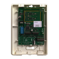
Specifies mounting the ATS1236 expander on any interior wall.

Mounting ATS1236

Step-by-step instructions for physically installing the ATS1236 expander.

Connecting ATS1236

Detailed steps for connecting the ATS1236 to the ATS control panel bus.

Wiring specifications

Details on cable length, gauge, diameter, and area for ATS1236.

Jumpers

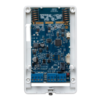
Information on TERM jumper (J2) and Relay output jumper (J5) settings.

DIP switch

Each wireless DGP requires a unique address set via DIP switches.

LEDS

Zone and output numbering

Table mapping zones and outputs for the control panel and DGPs.

Tamper

Relay

Programming

Signal level

Specifications

Regulatory information

Product warnings and disclaimers

Certification

Contact information

Related product manuals