77
3 3 Braking Braking SystemSystem
The braking system includes operation of the hand brake and foot brake. The hand brakeThe braking system includes operation of the hand brake and foot brake. The hand brake
consists of a lever and cable; the foot brake consists of a brake pedal, brake master cylinder,consists of a lever and cable; the foot brake consists of a brake pedal, brake master cylinder,
lines and brakes, etc. lines and brakes, etc. The brakes are maintenance-free wet disc The brakes are maintenance-free wet disc brakes.brakes.
Brake master cylinderBrake master cylinder
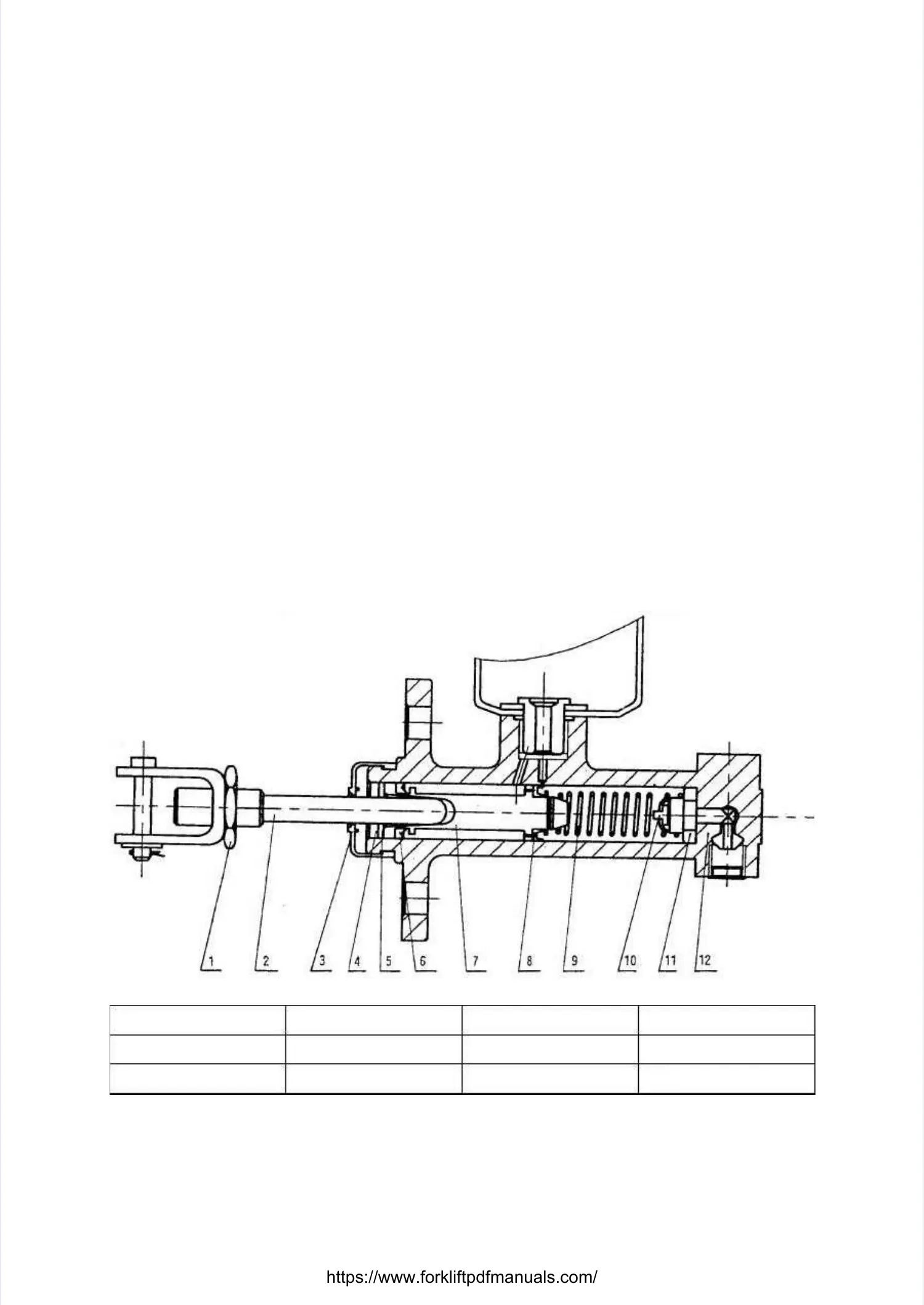
The brake master cylinder consists of a valve seat, check valve and return spring, as well as aThe brake master cylinder consists of a valve seat, check valve and return spring, as well as a
cup piston and auxiliary cup. The end cup piston and auxiliary cup. The end part is secured using a snap washer and retaining wire, thepart is secured using a snap washer and retaining wire, the
outer part is protected by a rubber dust cover, and the master cylinder piston is actuated by theouter part is protected by a rubber dust cover, and the master cylinder piston is actuated by the
brake pedal via a pushrod. When the brake pedal is depressed, the pushrod pushes the pistonbrake pedal via a pushrod. When the brake pedal is depressed, the pushrod pushes the piston
forward and the brake fluid in the pump flows back to the reservoir via the return port until theforward and the brake fluid in the pump flows back to the reservoir via the return port until the
main cup blocks the return port. Once the main cup pushes past the return port, the brake fluid inmain cup blocks the return port. Once the main cup pushes past the return port, the brake fluid in
the front chamber of the master cylinder is compressed and opens the check valve, therebythe front chamber of the master cylinder is compressed and opens the check valve, thereby
flowing through the brake line to the wheel cylinders. This forces each wheel cylinder pistonflowing through the brake line to the wheel cylinders. This forces each wheel cylinder piston
outward so that the outward so that the brake shoe friction plate contacts the brake drum, thus causing the brake shoe friction plate contacts the brake drum, thus causing the vehicle tovehicle to
decelerate or brake. At this point, the piston's rear chamber is replenished with brake fluid fromdecelerate or brake. At this point, the piston's rear chamber is replenished with brake fluid from
the return and inlet ports. When the brake pedal is released, the pistons are forced back by thethe return and inlet ports. When the brake pedal is released, the pistons are forced back by the
pressure of the return spring. At the same time, the brake shoe return spring forces the brake fluidpressure of the return spring. At the same time, the brake shoe return spring forces the brake fluid
in each brake wheel cylinder back through the check valve to the master cylinder (the frontin each brake wheel cylinder back through the check valve to the master cylinder (the front
chamber of the piston). The piston returns to chamber of the piston). The piston returns to its original position and the brake fluid in the its original position and the brake fluid in the mastermaster
cylinder flows back through the return port into the tank. The pressure of the check valve iscylinder flows back through the return port into the tank. The pressure of the check valve is
adjusted until it reaches a certain ratio of the residual pressure in the brake line and brake wheeladjusted until it reaches a certain ratio of the residual pressure in the brake line and brake wheel
cylinders, so as to correctly position the wheel cylinder cups to prevent oil leakage, as well ascylinders, so as to correctly position the wheel cylinder cups to prevent oil leakage, as well as
eliminate the possibility of air eliminate the possibility of air resistance during hard braking.resistance during hard braking.
1. 1. Lock Lock nut nut 2. 2. Pushrod Pushrod 3. 3. Dust Dust cover cover 4. 4. Retaining Retaining wirewire
5. 5. Retaining Retaining washer washer 6. 6. Auxiliary Auxiliary cup cup 7. 7. Piston Piston 8. 8. Main Main cupcup
9. 9. Spring Spring 10. 10. Check Check valve valve 11. 11. Valve Valve seat seat 12. 12. Pump Pump bodybody
Figure Figure 3-1 3-1 Brake Brake master master cylindercylinder
 Loading...