UV Sensor Error: If the UV Sensor Probe is not connected to the UV
power source, or if communication with sensor is not possible, the error
code E3 will be displayed. Verify that the sensor plug is fully inserted into
the UV power source before replacing the UV Sensor Probe. The system
also includes a sensor self test mode which is automatically executed if
the diagnostic display is activated. If the sensor fails the self test, the E7
error code is displayed and the sensor will need to be replaced.
Display & ERROR Codes Summary
The UV power source displays the following codes to announce system
status and/or problems. If more than 1 code is applicable, all active
codes will be displayed in sequence.
E1 – Low UV Alarm
E3 – Sensor Communication Error
E4 – Alarm Override Active
E5 – Change Lamp Reminder
E6 – Lamp Life Expired – Change lamp
E7 – Sensor Self Test Failure
oh – chamber over heat
Operating and Maintenance
Your UV system is on continuously during normal use.
After periods of not using your water supply exceeding 2-3 days, it is
recommended to open all faucets and flush your plumbing lines for a
minute or two.
Caution: Protect your unit from freezing. Drain all water from the unit if
freezing temperatures exist.
Ultraviolet lamp replacement: The ultraviolet lamp located inside the
chamber will operate effectively, around the clock, for approximately one
year. While the lamp will light longer than this, the UV light penetration
may fall below the prescribed safety level. Therefore, annual lamp
replacement is necessary regardless of apparent condition.
Replacing the UV lamp and cleaning the quartz sleeve
Note: Do not touch the lamp or the quartz sleeve with your fingers.
Handle by ends only or wear soft gloves.
Unplug the system from the electrical outlet, turn off all water supplies
to the unit, and de-pressurize system
Carefully extract the lamp connector from the sleeve gland nut
assembly to expose just the top of the lamp. While holding the lamp
base firmly, remove the lamp connector. Caution: lamp base can be
very hot – be careful not to drop lamp into quartz sleeve as it is easily
broken.
Carefully slide the UV lamp out of the quartz sleeve and discard
according to local disposal regulations.
Remove the quartz sleeve by loosening the gland nut(s) and carefully
extracting it from unit. Caution: The quartz sleeve is fragile and is easily
chipped or broken – use care when removing or installing.
Clean the quartz sleeve with a vinegar solution or any readily
available scale removal product (Limeaway, CLR etc.)
Re-install the quartz sleeve – replace “O” ring(s) if they appear
damaged.
Install new lamp by reversing procedure described in step 2 above.
Slowly open water supply valve and purge air from system – verify
that there are no leaks before reconnecting to AC power.
RESETTING THE LAMP CHANGE TIMER
The lamp change timer is reset by disconnecting the UV power
source from the AC supply, waiting for fifteen seconds and reconnecting
to the AC supply while depressing and holding the timer reset button.
The UV power source will emit a solid three second beep indicating that
the reset was successful. The reset button can now be released.
It is not possible to reset the lamp change timer unless the timer is
in the grace period, lamp change, or lamp failure alarm mode. If you
need to reset the lamp change timer prior to the end of one full year
there are special instructions included with all replacement lamps
describing the necessary procedure.
LOW UV ALARM
When the UV intensity level falls below 40mj/cm
2
, the system enters the
Low UV Alarm state and the E1 error code is displayed. If installed, the
solenoid valve will shut off water flow.
The Low UV Alarm Flow Chart on page 9 simplifies resolving Low UV
Alarm conditions.
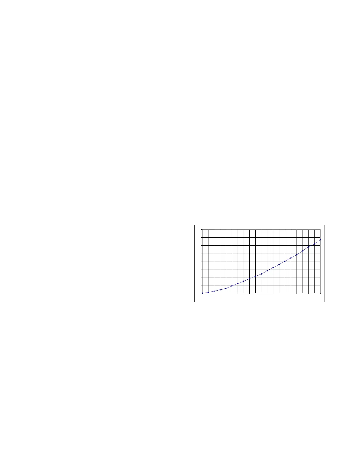
0
10
20
30
40
50
60
70
80
0 10 20 30 40 50 60 70 80 90 100
UVT% ESTIMATOR CHART
note 1
Note 1
- Chart is only valid with new lamp, sleeve and
sensor.
- operate system for thirty minutes and allow water to
flow for five minute before taking reading.
- If UV dose reading below the alarm threshold of
40mj/cm
2
use diagnostic display function to read
dose level.
- Validate system performance by rinsing and filling
disinfection chamber with water of known quality.
eg ( bottled water )
© COPYRIGHT 2019 UVDynamics – a Castle Circuits Inc. Business Group All RIGHTS RESERVED
 Loading...