Installation Instructions, Viper 2000 Control System
PRD0167E01en UWE Verken AB 3(6)
Footnotes
1. If the flap motor drive has an additional position
feedback, the flaps can be positioned in a
selectable number of intermediate positions. If left
unconnected the flaps will go all the way to their
respective mechanical stop positions.
2. This option is added for the case that analog
positioning of valve control motors is required. If a
single solenoid is to be used - connect the coil
between ground and either the inverted or non-
inverted output.
3. These outputs are added in order to make it
possible to use only the control unit as a
compartment controller.
4. The feedback potentiometers can be connected
directly between GND and +24V. Variations of
supply voltage are internally compensated.
Relay + AC : CO2 12 pole
AC Ice detection <5V = Ice CO2:1 Digital input
AC HP In series with Clutch activation CO2:2 Digital input
AC LP In series with Clutch activation CO2:3 Digital input
Defroster fan speed 2 Relay driver output CO2:4 Solid state outp. 1.9A
Defroster fan speed 3 Relay driver output CO2:5 Solid state outp. 1.9A
AC OverTemp <5V = Compr. over tmp CO2:6 Digital input
AC Condenser fan Contactor driver CO2:7 Solid state outp. 2.2A
Defroster fan speed 1 Relay driver output CO2:8 Solid state outp.1.9A
Defroster fan speed PWM + 20 kHz Duty Cycle modulated differential
output for direct interface with PWM switch.
NonInv.
CO2:9 EIA RS485 transmitter out-
put. 15kV ESD protection,
slew rate limited.
AC Compressor Clutch Direct drive CO2:10 Solid state outp. 5.7A
Whisper heating fan (Rec. Blower) Relay driver output CO2:11 Solid state outp. 1.9A
Defroster fan speed PWM - As CO2:9 Inverted CO2:12 As CO2:9
Power supply + Communication: CO3 9 pole
Recirculation blower for guide Relay driver output 3) CO3:1 Solid state outp. 1.9A
Booster pump Relay driver output 3) CO3:2 Solid state outp. 1.9A
Auxilliary Heater Relay driver output 3) CO3:3 Solid state outp. 1.9A
Batt+ Battery+ / Standby CO3:4 Power 10A / 30mA
Generator + >7V = Engine running CO3:5 Digital input
CAN L Transceiver PCA82C251 CO3:6 Communication Line
GND Chassies Ground CO3:7 POWER GND
Supply + Master Switch (+30) / System wake up CO3:8 Power input 1A
CAN H Transceiver PCA82C251 CO3:9 Communication Line
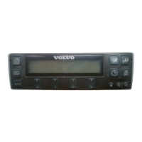
Table 1: Display unit
Description Comment
See
footnote
Pin Type
 Loading...