Installation Instructions, Viper 2000 Control System
PRD0167E01en UWE Verken AB 2(6)
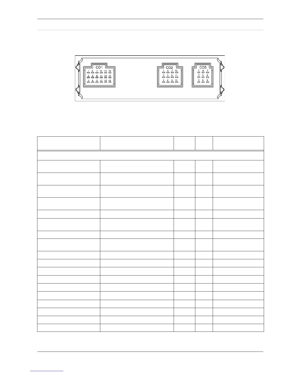
Connection of display unit (syst 1)
Connections to components should be performed according to
the table below::
Table 1: Display unit
Description Comment
See
footnote
Pin Type
Defroster: CO1 18 pole
Valve, Defroster circuit Open = 0V. Direct Drive / Motor valve driver.
Inverted.
2) CO1:1 Solid state outp. 1.9A
Valve, Driver’s convector circuit Open = 24V. Direct Drive / Motor valve
driver. Non-inverted
2) CO1:2 Solid state outp. 1.9A
Valve, Defroster circuit Open = 24V. Direct Drive / Motor valve
driver. Non-inverted
2) CO1:3 Solid state outp. 1.9A
Valve, Driver’s convector circuit Open = 0V. Direct Drive / Motor valve driver.
Inverted
2) CO1:4 Solid state outp. 1.9A
Temp sensor, Defroster air CO1:5
Analog NTC 4,7k
Ω
Valve, Defroster circuit position feed-
back
Open = High Voltage 2) ,4) CO1:6 Analog 0 - 33V
Flap Fresh/Recirc, defroster air Rec = +24V. Source / sink CO1:7 Solid state outp. 1.9A
Valve, Driver’s Convector circuit pos
feedback
Open = High Voltage 2) ,4) CO1:8 Analog 0 - 33V
Temp sensor GND, defroster air CO1:9 Sensor ground
Flap Fresh/Recirc defroster air Rec = 0V. Source / sink CO1:10 Solid state outp. 1.9A
Temp sensor, Outside air CO1:11
Analog NTC 4,7k
Ω
Temp sensor GND, Outside air CO1:12 Sensor ground
Flap Floor/Screen Scr = +24V. Source / sink CO1:13 Solid state outp. 1.9A
Temp sensor, Driver’s place CO1:14
Analog NTC 4,7k
Ω
Temp sensor GND, Driver’s place CO1:15 Sensor ground
Flap Floor/Screen Scr = 0V. Source / sink CO1:16 Solid state outp. 1.9A
Flap Floor/Screen, position feedb. Floor = High voltage Scr = 0V 1) ,4) CO1:17 Analog 0 - 33V
Flap Fresh/Recirc, position feedb. Recirc= High voltage Fre = 0V 1) ,4) CO1:18 Analog 0 - 33V