EasyManua.ls Logo

V-ZUG CookTopInduction V4000 CTI4T64 Series User Manual

V-ZUG CookTopInduction V4000 CTI4T64 Series
9 pages
To Next Page IconTo Next Page
Page #1 background imageLoading...
Page #1 background image
Installation instructions
CTI4T64/74
CookTopInduction V4000
Glass ceramic hob
1065985-R01
23/04/2019
1065985-R01
1
The appliance should be installed by qualified personnel only. Each step must be carried out and checked in full in
the order specified.
Validity
These installation instructions apply to the following models:
Model number With normal mounting frame With DualDesign With oversize mounting frame
31115 CTI4T64MMSLC, CTI4T64MMSOLC CTI4T64MMSLD,
CTI4T64MMSOLD
CTI4T64MMSLU, CTI4T64MMSOLU
31116 CTI4T74MMSLC, CTI4T74MMSOLC CTI4T74MMSLD,
CTI4T74MMSOLD
-
General notes
If installing into a combustible material, the guidelines and standards for low-voltage installations and fire protection
must be strictly observed.
Identification plate
The identification plate is located next to the connection plate.
Connection plate
Identification plate
Affix the second identification plate (supplied) in an accessible position behind the front of the fitted cabinet beneath the appliance.
Question and Answer IconNeed help?

Do you have a question about the V-ZUG CookTopInduction V4000 CTI4T64 Series and is the answer not in the manual?
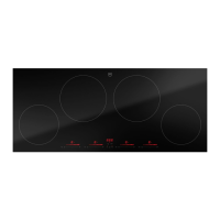
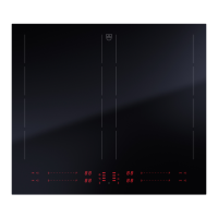
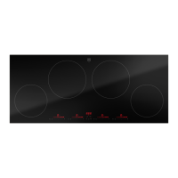
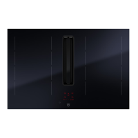
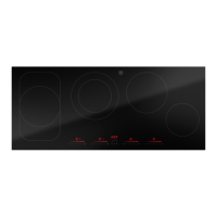
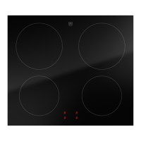
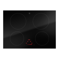
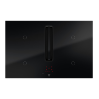
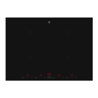
V-ZUG CookTopInduction V4000 CTI4T64 Series Specifications

General IconGeneral
TypeInduction Hob
Number of Zones4
Control TypeTouch Control
Power Levels9
Installation TypeBuilt-in
Total Power7.4 kW
TimerYes
Automatic Pan DetectionYes
Boost FunctionYes
ColorBlack
MaterialGlass ceramic
Safety FeaturesChild Lock, Residual Heat Indicator

Summary

Validity

Model Applicability

Lists the specific appliance models to which these installation instructions apply.

General notes

Combustible Material Installation Safety

Observe guidelines for low-voltage installations and fire protection when installing into combustible materials.

Identification Plate Information

Location of the identification plate and placement of a second plate.

Electrical connection

Mains Voltage and Connection Requirements

Details requirements for electrical connections by qualified personnel and mains voltage specifications.

U400 Error Message

Explains the U400 error, indicating a pole conductor connected to the neutral terminal.

Ventilation

Ventilation Requirements

Specifies the necessary space and airflow path for adequate ventilation of the appliance.

General information about installation

Worktop and Ventilation Space

Ensures a flat worktop for sealing and adequate ventilation space beneath the appliance.

Overlying installation with normal mounting frame

Installation Steps

Procedure for creating the cut-out and seating the appliance onto the work surface.

Overlying installation

Installation Steps

Procedure for creating the cut-out and seating the appliance onto the work surface.

Flush installation

Installation Procedure

Steps for cut-out creation, appliance preparation, cementing, and electrical connection.

Installation with oversize mounting frame

Installation Notes

Details on using oversize frames, including replacement scenarios and fixing methods.

Variable areas of the special cut-out dimensions

Reinforcement and Brace Arrangement

Guides on reinforcing cut-outs with steel covers and arranging adjusting braces.

Installation of the ventilation protective plate with 3 mm ventilation gap at the front

Ventilation Protective Plate Requirements

Specifies the need for a protective plate and the required distance for adequate ventilation.

Cool Air Supply for Drawer/Cabinet Installation

Ensures sufficient cool air supply for ventilation when a drawer or cabinet is installed below.

Related product manuals