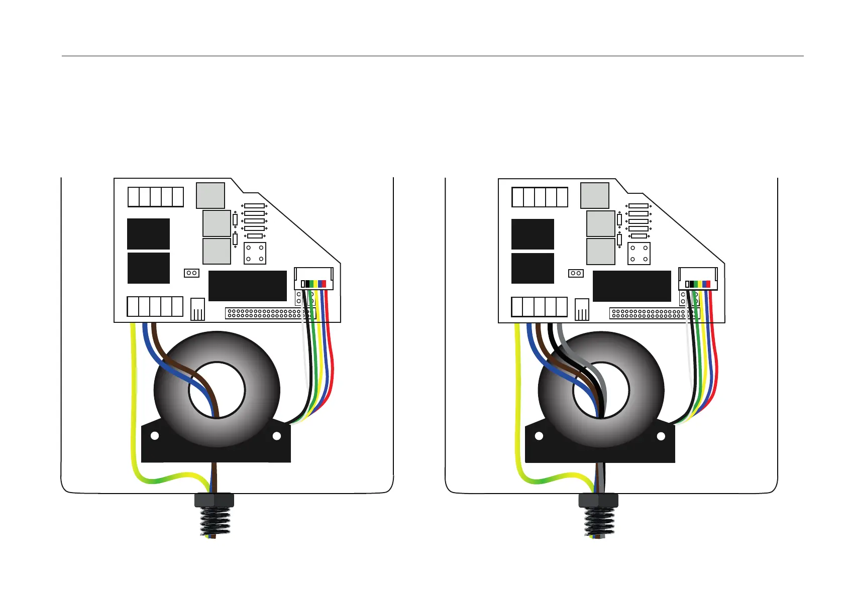
LEAK DETECTOR INSTALLATION DIAGRAMS
Single-phase installation
Run the following wires from the power board to the
hose: Neutral (blue) and Phase 1 (brown) inside the coil.
Always leave the earth wire (yellow and green) outside.
Three-phase installation
Run the following wires from the power board to the hose:
Neutral (blue), Phase 1 (brown), Phase 2 (black) and Phase 3
(grey) inside the coil. Leaving always the earth wire (yellow
and green) outside.
PE
N
R
T
S
P2
1
J1
P3
P4
PE
N
R
T
S
2
3
1
4
Power
board
Coil
Three-phase
installation
Leak
detector
connector
Charging
hose
Trydan
Housing
PE
N
R
T
S
P2
1
J1
P3
P4
PE
N
R
T
S
2
3
1
4
Power
board
Coil
Single-phase
installation
Leak
detector
connector
Charging
hose
Trydan
Housing