Do you have a question about the Vaillant eloBLOCK VE 21 /14 EU I and is the answer not in the manual?
| Model | eloBLOCK VE 21 /14 EU I |
|---|---|
| Power Output | 21 kW |
| Heating Capacity | 21 kW |
| Rated Output | 21 kW |
| Energy Efficiency Class | D |
| Efficiency (ErP) | 36% |
| Rated Voltage | 400 V |
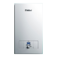
| Product Type | Electric Boiler |
| Fuel Type | Electric |
| Operating Pressure (Heating) | 3 bar |
| Flow Temperature Range | 20-85°C |
| Electrical Connection | 400 V / 50 Hz |
| Protection Class | IPX4 |
| Nominal Heat Output | 14-21 kW |
Classification of warnings by danger severity using signal words and symbols.
Potential dangers and material damage from incorrect product operation.
Specifies the product's intended application for heating and hot water generation.
Provides essential safety guidance for operation and installation.
Highlights work requiring competent persons and qualified personnel.
Emphasizes the need for installing safety devices and adhering to standards.
Warns about the danger of touching live components and required precautions.
Advises on handling hot components only after they have cooled down.
Warns about scalding risks at hot water draw-off points, especially for vulnerable groups.
Outlines conditions and restrictions for selecting the installation location.
Provides instructions and conditions for securely mounting the product on a wall.
Step-by-step guide for attaching the product bracket and hanging the unit.
Details on connecting the heating flow and return lines according to standards.
Instructions for connecting the drain line to the expansion relief valve outlet.
Guidance for qualified electricians on electrical connection procedures.
Steps for installing the power supply cable and connecting terminals.
Details on properly connecting the earth cable for safety.
Instructions for connecting various external controls and accessories.
Instructions for connecting the product to a single-phase power supply.
Guidance on verifying and treating heating water quality for optimal performance.
Guide to resolving faults indicated by error codes (F.xx).
Troubleshooting steps for pump faults indicated by the status LED.
Procedure for addressing faults caused by a jammed relay (F.180).