Electrical installation 5
0020151756_01 Heat pump control module Installation instructions 5
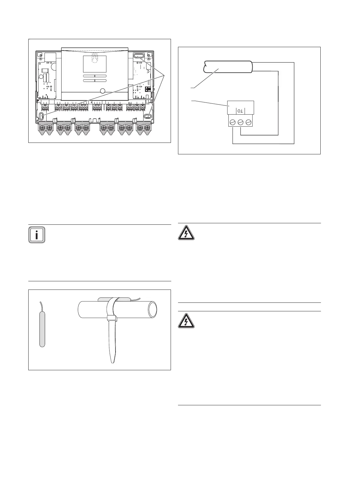
4.2 Installing the product
PE N L
230 V~
+ -
Bus VF1 SP1
PE N L
230 V~
AF DCF
DCF/AF ME EVU
PE N L
MA1
PE N L
MA2
PE N
Auf
Zu
UV1
PE N 1 2
ZH
2 1 2 1
2 1
2 1
1
1. Mount the product and the supplied installation access-
ory on the wall. Use the fixing points (1) for this.
2. Connect the product. (→ Page 6)
4.3 Closing the casing
1. Insert the casing cover at the top into the hinges.
2. Fold down the casing cover.
3. Screw the bolt into the underside of the casing.
4.4 Installing the VR 10 standard sensor
Note
You can use the VR 10 as a cylinder temperature
sensor (for example, as an immersion sensor
in a cylinder dry pocket), as a flow temperature
sensor (for example, in the low loss header) or
as a surface mount sensor. We recommend that
the pipe with the sensor be insulated to ensure
optimum temperature recording.
▶ If you use the VR 10 as a surface mount sensor, secure
the VR 10 to a return/flow pipe using the enclosed strap.
4.5 Installing the external temperature sensor
Installing the external temperature sensor
1 Connection cable to the
VRC 693 external temper-
ature sensor
2 Connector in the product
▶ Install the external temperature sensor in accordance
with its enclosed installation manual.
5 Electrical installation
Danger!
Risk of death from live connections!
There is a risk of death from electric shock
when working on the open product and in the
electronics box of the heat pump.
▶ Before working on the product and in the
heat pump's electronics box, switch off the
power supply.
▶ Secure the power supply against being
switched on again.
Danger!
Risk of damage caused by incorrect in-
stallation.
Connecting wires that have been stripped
too far may cause short circuits and damage
the electronics if a strand accidentally comes
loose.
▶ Only strip the outer sheathing of flexible
cables to a maximum of 2.5 cm to prevent
short circuits.
▶ Lay the lines correctly.
▶ Use strain reliefs.
 Loading...