4947182
Installation Procedure
1. Connect PagePac® 6 Plus to the incoming telephone line(s). Connections are shown in Figure 2.
2. Connect PagePac 6 Plus to line jack(s) on telephone system.
3. Connect speakers to PagePac 6 Plus with RCA-type phono plugs and “B” crimp-type wire
connectors (provided).
4. (Optional) You may connect an external music source such as a FM tuner, tape deck, leased source,
etc.
5. Connect the power supply to an AC outlet (120 VAC, 60 Hz). The LED on the PagePac 6 Plus back
panel (below the power cord) will illuminate.
NOTE: If optional music source is used, it must have a 600 Ohm less than 1 volt output to drive the
PagePac 6 Plus (usually the output that would drive an auxiliary head set). Anything greater than this
can harm the PagePac 6 Plus and void the warranty.
Single Line—Use Line 1 Connection Only
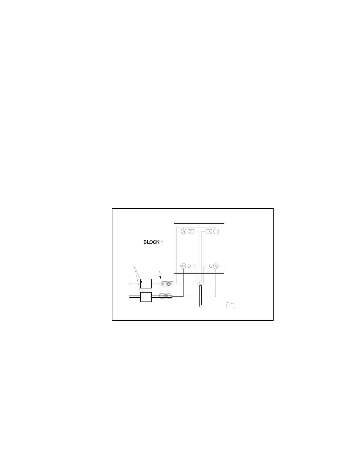
1. Install the first connecting block and attach the incoming line(s) to the block.
2. Attach the half-modular connecting block, and connect the other end to the PagePac 6 Plus
(see Figure 2).
3. Install the second connecting block and attach the line(s) to the telephone(s).
4. Attach the second half-modular cord to this block and connect the other end to the Pagepac 6 Plus.
Figure 2. Attaching the Half-Modular Cord
WRAP UNUSED WIRE
AROUND CABLE
TYPE 42A CONNECTING BLOCK
RED
G
R
B
Y
GREEN
RED
GREEN
LINE 1
LINE 2
O
ENTRAL
FFICE
YELLOW
LINE 2
BLACK
LINE 2
RED GREEN
HALF MODULAR CORD
TP PAGEPAC 6 PLUS
"TO TEL. CO. J4"
UL 497A
SECONDARY
PROTECTORS
Technical Manuals Online! - http://www.tech-man.comTechnical Manuals Online! - http://www.tech-man.com