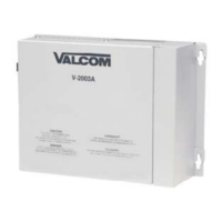
4
Switch Selectable Options
Loop start and ground start access are switch
selectable on the V-2003A/V-2003AHF.
SW1: Selects the loop or ground start option
for system tip and ring.
SW5: Selects the loop/ground start option
for override tip and ring (See Figure 3 for
location). A 12-position dip switch is provided
for programming zone capabilities. Figures 1
and 3 indicate the function of each dip switch
(i.e., the feature it activates).
NOTE: For one-way paging on a V-2003A,
the dip switch for the talkback feature on a
one-way zone must be set to "Off: (No zone x
talkback).
The V-2003A/V-2003AHF requires a power
down reset in order to implement dip switch
changes (Unplug AC power from the
V-2003A/V-2003AHF for a minimum of 30
seconds then reconnect to effect a dip
switch change).
FIGURE 1
SW3 Up (OFF) Down (ON)
12 No Zone 3 Music Zone 3 Music
11 No Zone 3 Tones Zone 3 Tones
10 No Zone 3 Talkback Zone 3 Talkback
9 No Zone 2 Music Zone 2 Music
8 No Zone 2 Tones Zone 2 Tones
7 No Zone 2 Talkback Zone 2 Talkback
6 No Zone 1 Music Zone 1 Music
5 No Zone 1 Tones Zone 1 Tones
4 No Zone 1 Talkback Zone 1 Talkback
3 System Dial Tone No System Dial
Tone
2 System Ringback No System Ringback
Tone* Tone*
1 System Repeated No System
Repeated
Alert* Alert*
* Repeated system alert tone is available
only with the V-2003AHF. Ringback tone
provides an alert tone over speakers only
on handsfree outputs with the V-2003AHF.
Wiring Instructions for Loop or Ground Start
Access
A connection block with a 50 pin female
amphenol connector must be used to
crossconnect speakers and inputs. See Figure
2 for 66 block pinouts.
___1. Make certain Battery Feed switch
(SW2) is ON (In the Down position, See
Figure 3).
___2. Ascertain SW1 is in proper position.
SW1 should be in the UP position for
loop start operation or in the DOWN
position for ground start operation.
GROUND START NOTE: When using ground
start access, a ground strap must be connected
between the telephone system ground and a
ground output (+) of the V-2003A/V-2003AHF
(See
Figure 2).
___3. Plug 50-pin female Amphenol connector
into J2 of the V-2003A/V-2003AHF.
If a modular cord is used for Tip and Ring
connections, connect (J1) RJ11 Tip and Ring to
the appropriate C.O. line position of the phone
system.
For punchdown block Tip and Ring connections,
connect Tip of the telephone system C.O. line
position or loop or ground start trunk to the Tip
(W/BL) pin and Ring to the (BL/W) of the cross
connect block.
Connection of One-Way Amplified Speakers
Using twisted pair telephone wire, connect:
Zone 1 Speaker Tip, Ring -R/BL, BL/R
Zone 1 Speaker -24VDC -R/O
Zone 1 Speaker GND -O/R
Zone 2 Speaker Tip, Ring -R/G, G/R
Zone 2 Speaker -24VDC -R/BR
Zone 2 Speaker GND -BR/R
Zone 3 Speaker Tip, Ring -R/S, S/R
Zone 3 Speaker -24VDC -BK/BL
Zone 3 Speaker GND -BL/BK
NOTE: The V-2003A provides external power
of 20 power units (1 Amp of -24VDC) to operate
one-way amplified speakers. Additional power
supplies are required for a quantity of speakers
using power over the 20 power units. The
V-2003AHF supplies external power of 10 power
units (1/2 Amp at -24VDC) to operate one-way
amplified speakers. Additional power supplies
are required for a quantity of speakers using
power over the 10 power units.
When using additional power supplies, make
certain:
1) The -24VDC outputs are not connected to
each other or to the V-2003A/V-2003AHF.
2) Each speaker is connected to only one
power source (Talkback speakers do not
require power).
3) All power supply grounds are connected
directly to a copper cold water pipe earth
ground. The use of an electrical ground
in place of a direct cold water pipe ground
may introduce noise into the paging
system.

 Loading...