2
INSTALLATION
Cabling
A 25 pair cable with a female amphenol connector
should be run from the feedback eliminator to a 66B
type punchdown block. The cable should be terminated
on the block in standard color code order. (See Figure
2).
Mounting
NOTE: DO NOT install the V-9962 or its wiring
closer than 18" to a power supply or any equipment
that generates electrical noise.
___ 1. Using four #6 - 1/2" wood screws, mount the
feedback eliminator in a vacant space on the
backboard.
___ 2. Mount a 66B type punchdown block near the
unit and label the block per Figure 2.
___ 3. Connect the 25 pair cable to the punchdown
block per standard color code order.
___ 4. Connect the female amphenol connector to the
V-9962.
Connections
___ 1. Connect zone output from a 600 ohm page port
or Valcom page control to Audio In Tip
(W/BL) and Audio In Ring (BL/W) on the
punchdown block. (See Note at end of this
section).
___ 2. Connect page enable contact closure (if
available - this is an optional connection) to
COM (R/BL) and RECORD (BL/R) on the
punchdown block.
___ 3. Connect Tip lead or terminal of amplified
speaker(s) to output 2; speaker level 8Ω
(W/BR) on the punchdown block.
___ 4. Connect Ring lead or terminal of amplified
speaker(s) to output 2; speaker level return
(BR/W) on the punchdown block.
___ 5. Connect -24Vdc from a filtered -24Vdc power
supply to pin 24 (BR/V) on the punchdown
block.
___ 6. Connect GND of the power supply to pin 49
(V/BR) on the punchdown block.
___ 7. Plug in power supply.
___ 8. The POWER ON LED on the V-9962 should
illuminate. (IF POWER ON LED does not light,
then using a voltmeter, measure voltage
between power terminals with negative probe
at pin #24 and positive at pin #49. If reading is
reversed, unplug power supply, verify V/BR
and BR/V pairs are properly connected at the
punchdown block and connector).
See Figure 3 for simplified block diagrams of typical
configurations.
NOTE: The input level must be attenuated using a V-
1092 to prevent distortion if exceeding nominal input
levels for the V-9962; i.e., when used on a zone of
Valcom talkback page control (for one-way paging).
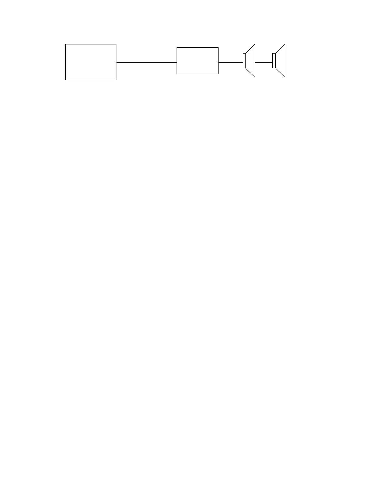
Valcom
Page Control
Unit
Zone
Output
V-9962
Up to 150 Valcom
Amplified Speakers
FIGURE 1 - SIMPLIFIED BLOCK DIAGRAM OF A TYPICAL INSTALLATION
 Loading...