Performance may vary depending on, but not limited to cell usage and application.
If cell is used outside specifications, performance will diminish. All specifications
are subject to change without notice. All information provided herein is believed,
but not guaranteed, to be current and accurate. Copyright © 2005-2008 Valence
Technology, Inc.
Revision Date October 2008
12303 Technology Blvd., Suite 950, Austin, TX 78727, USA
Phone (888) VALENCE or +1 (512) 527-2900, Fax +1 (512) 527-2910
Unit 63 Mallusk Enterprise Park, Mallusk Drive, Newtownabbey, UK
Phone +44(0) 28 9084 5400, Fax +44(0)28 9083 8912
Email: sales@valence.com
, Web site: www.valence.com
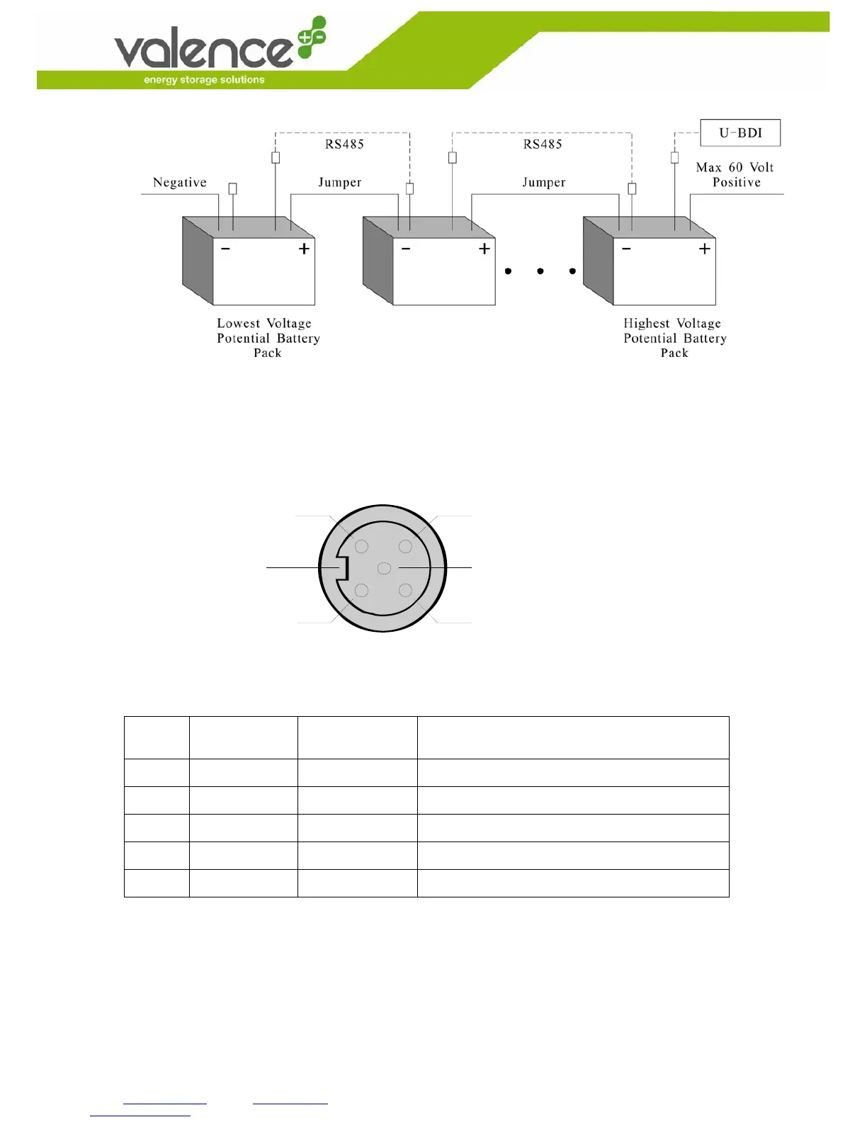
Figure 4: Installation of U-Charge
®
RT power systems in Series.
A RS-485 bus is used as the communication method between a U-Charge
®
RT power system
and its U-BMS. Each battery contains one male and one female connector which are wired in
parallel to make it possible to daisy-chain communication cables. Figure 5 and Table 3 describe
the pin-out of the two 5-pin M12 connectors:
Mechanical Key
1
4
3
5
Figure 5. Female type M12 connector
Pin Signal
Name
Pin Type Description
1
N/A N/A Shield
2
VCC (+5) Power Power supply for the RS-485 transceiver
3
GROUND Power Ground for the RS-485 transceiver
4
B(+) Signal B signal from the RS-485 transceiver
5
A (-) Signal A signal from the RS-485 transceiver
Table 3: Pin-out of the RS-485 communication ports in U-Charge
®
RT power system