2.2 Overview
The Zeus board may be mounted inside the LP12 turntable on a Linn (or compatible)
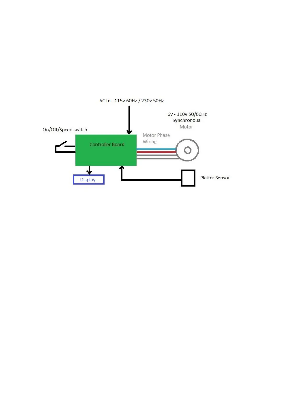
cross brace. The minimum connections are mains power and motor wiring. It’s
possible to operate the board with just these two connections, however, most users
will want the start/33/45/stop switch, the OLED display and IR sensor for adaptive
(PID) speed control.
Figure 1 - Pictorial wiring for a 2 phase synchronous motor
The on/off/speed switch is a standby switch. The board may be configured to go into a
low power sleep state after a period of inactivity.
The procedure for installation is in two parts. Basic installation and adaptive PID
speed control.
2.2.1 Connecting the FFC ribbon cables
Slide the black retaining clip forward about 1.5mm away from the connector – this
will release the latch. When connecting the cable back the contacts face towards the
PCB. Slide the blue tab in and push the black retaining latch back so it clicks into
place. This will lock the FFC cable in place. When inserting the FFC cables the
contacts on the FFC cables always face the PCB.