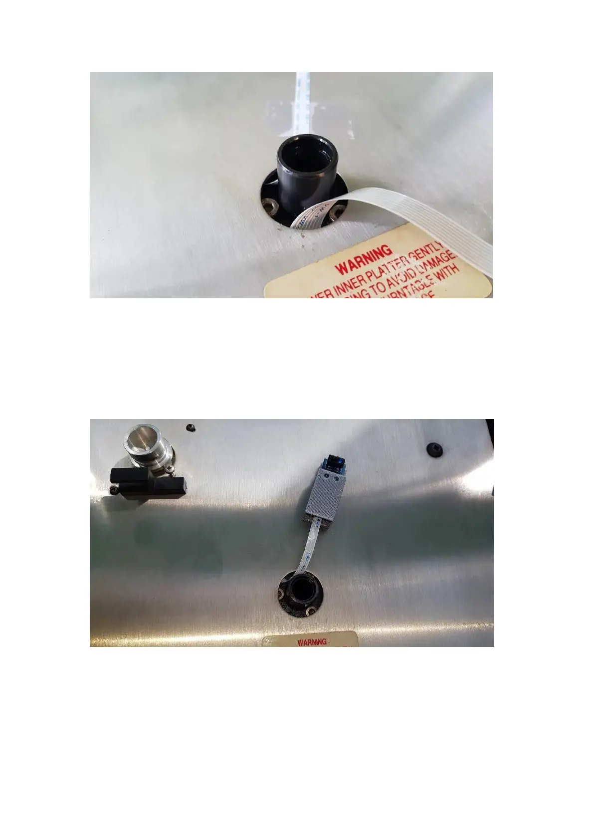
Position the IR sensor towards the inside edge of the outer platter. Lightly tack down
the FFC cable for the positioning test. Use either double sided sticky tape or a couple
of small balls of blue/white tack to stick down the IR sensor lightly. Connect the other
end of the 4 way FFC cable to connector P3 on the underside of the motor controller
PCB (silver contacts towards the PCB).
Position the IR sensor diodes to the outside of the platter. Use the supplied black label
approx. 10mm in width, and affix to the inside edge of the platter. Mount the IR
sensor close so that the transmitting and receiving diodes can register the passing of
the tape.