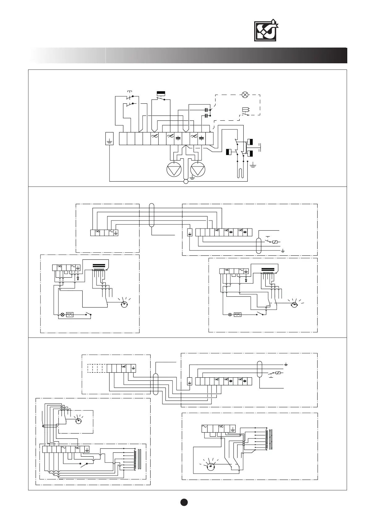
F1 Supply air fan
F2 Extract air fan
T1 Post-heating radiator regulating
thermostat 0...+25
°
C (Limitation)
T2 Overheat protector +80
°
C
T3 Antifreezing thermostat +4
°
C
R Post-heating radiator
K Capacitor
SS Safety switch
Wire colours:
m = black
r = brown
s = blue
F1
F2
K
TK
T1
m
s
s
s
s
s
s
m
m
m
m
m
L
N
N
1
L
m
T3
m
m
K
r
r
N
L
m
80°C
80°C
R
T2
1
s
L
1
m
+
V
-
W
2
3
Speed selector switch
(factory setting)
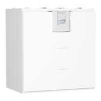
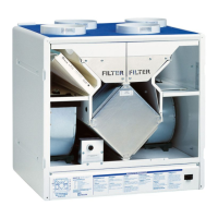
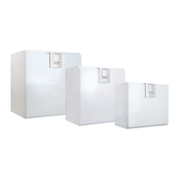
VALLOX 75/95
9
ELECTRICAL CONNECTIONS/ELECTRIC RADIATOR
3 X 1.5 S
L
10 A
N
N
1
L
N
L
1
L
L
N
L
3
2
N
INTERNAL ELECTRICAL
CONNECTION OF THE
HOODS
N
L
VALLOX 95/75
COOKER HOOD
PTXP(A) 27983
COOKER HOOD
PTX 27983
HOOD
Distribution
panel
L
3
2
3
0
V
1
6
0
V
1
2
0
V
7
0
V
L
N
9
0
V
1
3
5
V
1
8
0
V
1
5 X 1.5 S
2
3
PL 11
L
1
2
3
2
3
0
V
1
6
0
V
1
2
0
V
7
0
V
L
L
2
N
9
0
V
1
3
5
V
4
L
2
1
8
0
V
1
2
3
PL 11
0
4
N
L
3
N
VALLOX 75/95, 3510, external electrical connection with cooker hood PTX 27982 or PTXP(A) 27982
24
N
2
L
N
N
5 X 1.5 S
L
3 X 1.5 S
N
A
N
L
CONTROL CENTRE
1992A EK
3
1
L
L
N
L
NL
L
L
3
CONTROL CENTRE
N
N
L
13
2
1
10 A
VALLOX 95/75
Distribution
panel
CONTROL CENTRE
1992A
2
N
1
1
L
3
2
3
L
3
L
N
N
L
2
4
120 V
90 V
70 V
230 V
135 V
160 V
180 V
2
1
3
4
1
2
3
4
b
5
*
1
.
5
120 V
90 V
70 V
230 V
135 V
160 V
180 V
3
2
1
4
0
(Forced control centre doesn´t have a
"0" setting in speed selector switch)
VALLOX 75 / 95, model 3510, external electrical connection with control centre
VALLOX 75 / 95, model 3510, internal electrical connection
(Forced control centre doesn´t
have a speed selector switch)