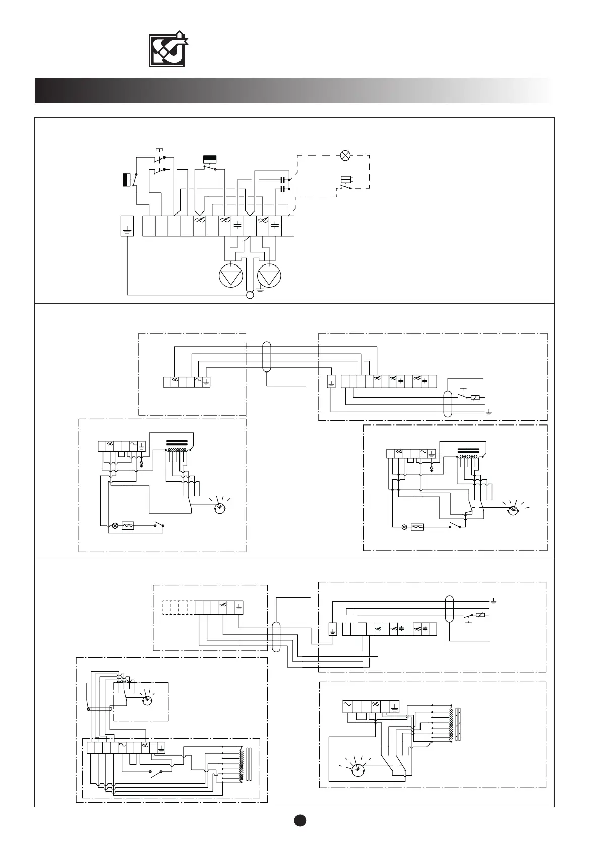
Speed selector switch
(factory setting)
(In a forced control centre there is no
position "0" in the speed selection switch.)
Distribution
panel
On/Off-switch
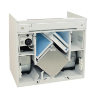
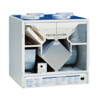
VALLOX 75/95
10
ELECTRICAL CONNECTIONS/WATER RADIATOR (VKL)
VALLOX 75/95 VKL, 3510, external electrical connection with cooker hood PTX 27982 or PTXP(A) 27982
VALLOX 75 / 95 VKL, model 3510, external electrical connection with control centre
VALLOX 75 / 95 VKL, model 3510, internal electrical connection
F1 Supply air fan
F2 Extract air fan
T1 Post-heating radiator regulating
thermostat 0...+25 °C (Limitation)
T2 Defrost thermostat +5 °C
K Capacitor
SS Safety switch
Wire colours:
m = black
r = brown
s = blue
T2
F1
F2
K
TK
m
s
s
s
s
s
m
m
m
m
m
L
N
N
1
L
T1
m
m
K
r
r
N
L
m
1
m
s
L
1
s
+
V
-
W
23
3 X 1.5 S
L
10 A
N
N
1
L
N
L
1
L
L
N
L
3
2
N
INTERNAL ELECTRICAL
CONNECTION OF THE
HOODS
N
L
VALLOX 95/75 VKL
HOOD
Distribution
panel
COOKER HOOD PTX 27982
230 V
160 V
120 V
70 V
L
L
2
N
4 X 1.5 S
90 V
135 V
180 V
1
2
3
L
1
2
3
PL 11
0
COOKER HOOD PTXP(A) 27892
L
3
230 V
160 V
120 V
70 V
L
N
90 V
135 V
180 V
1
2
3
PL 11
4
L
2
4
N
L
3
N
L
N
N
4 X 1.5 S
L
3 X 1.5 S
N
A
CONTROL CENTRE 1992A EK
N
1
2
3
1
L
L
N
L
NLL
L
3
3L
CONTROL CENTRE
N
N
L
2
13
2
1
10 A
VALLOX 95/75 VKL
4
120 V
90 V
70 V
230 V
135 V
160 V
N
L
3
L
N
N
L
CONTROL CENTRE 1992A
2
120 V
90 V
180 V
2
1
70 V
230 V
135 V
12
L
3
160 V
180 V
3
2
1
4
0
3
4
1
2
3
4
b
5*1.5
24
N
(Forced control centre has no switch A)