35
Model Code Page
21. Engine
1. 11. 2000
95--115
X100--X120
210 13
Cylinder head
420---engine have one cylinder head. Each cylinder has its
own inlet and exhaust ports located on either side of the head.
Between hot exhaust valves a cool inlet valve is fitted to bal-
ance the thermal load.
Cylinder head bolts are high tensile bolts which are tightened
up to yield limit using angle tightening princ iple. Due to the
large stretch the tightening forces are kept constant duringthe
whole lifetime and retightening is unnecessary.
The injector locations are machined directly into the cylinder
head. The inlet and exhaust valve guides are identicalandcan
be interchanged.In addition,theexhaust valves are equipped
with replaceable valve seat inserts.
Valve mechanism
The valve mechanism is operated by the camshaft which is lo-
cated in the cylinder block. The drive is transferred with the
help of tappets and pushrods. The camshaft gear wheel is
fitted with a press fit and fixed with a key. Each bearing is lubri-
cated by the force feed lubrication system through drilled oil-
ways in the motor block.
Crank mechanism
The crankshaft is forged from chrome alloy special steel and
is induction hardened at the bearing and sealing surfaces.
This makes it possible to grind bearings four times without a
new heat treatment. Gear wheels are located at the front end
of the crankshaft. They are a press fit, and drive the idler
wheel and oil pump. In addition, the front end of the crank-
shaft has splines for the hub of the V---belt pulley. An oil deflec-
tor ring is fitted between the hub and gear wheel, and a dust
shield is fitted on the hub in order to protect the seal.
The crankshaft is supported on the cylinder block by main
bearings which are placed on both sides of each cylinder.
Thus there is one main bearing more than cylinders. The
crankshaft thrust washers are placed in both sides of the rear-
most main bearing.
At the rear end of the crankshaft there is fitted a flywheel on
which is a press---fit a starter ring gear. The forged crankshaft
has an I---section cross---section. The bearing location at the
bottom end of the connecting rod is split, and the bearing cup
is secured by two special bolts and nuts. The upper part has
a wedge---shaped bearing location, in which the piston pin
bearing bushing is fitted with a press fit.
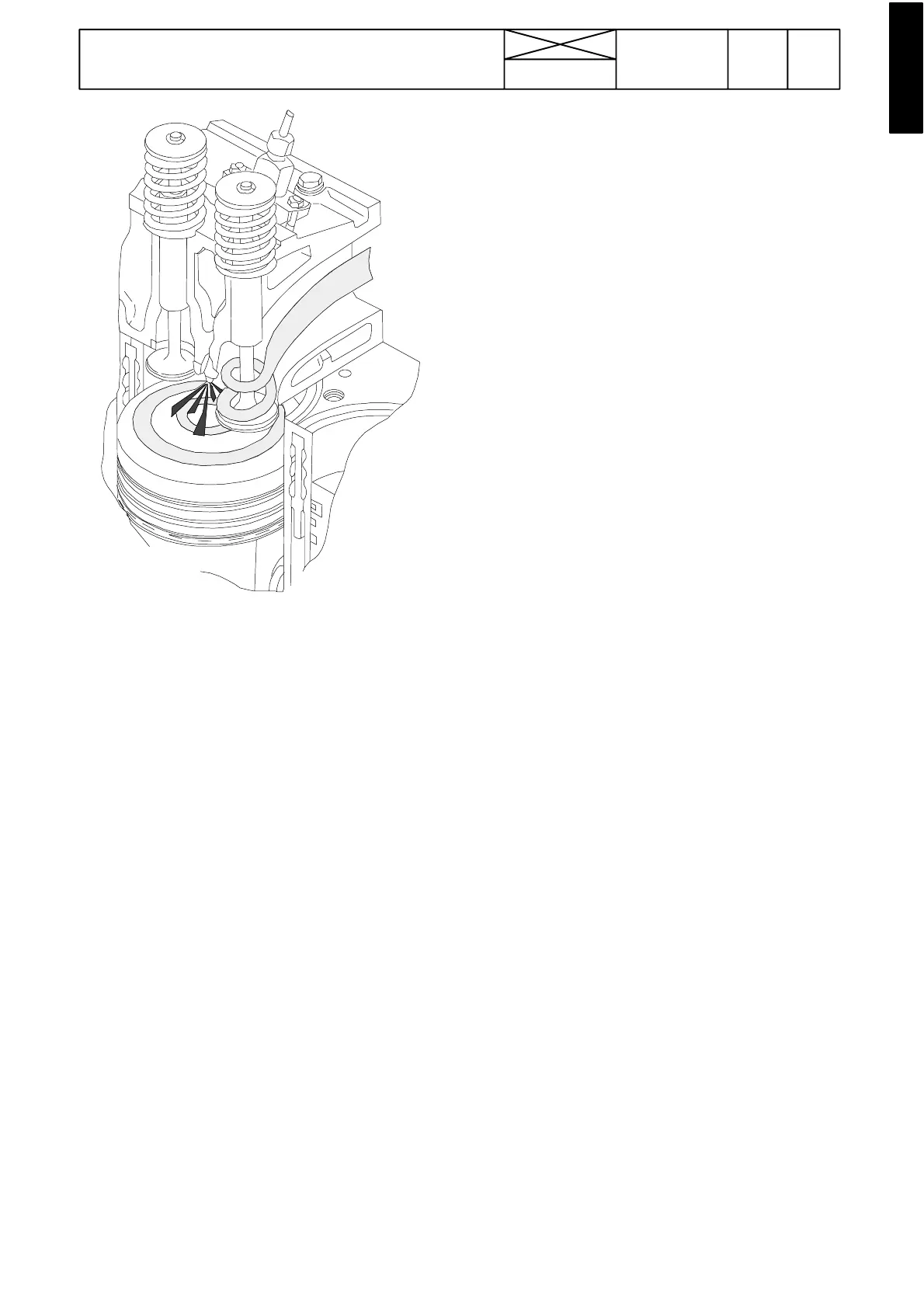
The piston is made of an eutectic aluminium allo y. In the
upper face of the piston there is a combustion chamber. The
shape of the chamber is intended to maximise the mixture of
air and fuel. The piston has three rings. The upper molyb-
denum---coated ring has a wedge---shaped cross---section.
On natural aspirated engines and on slight superchar ged
engines the upper ring is right---angled.Themiddleringistap-
ered and it fits into its groove. The taper taking up the clear-
ance. The oil control ring is spring loaded and it has a two---
stage, chromed scraping edge.
On the turbocharged engines the upper ring location is
formed in a cast iron ring which is cast in the piston. In addi-
tion, the piston on supercharged engines is graphite coated
to ensure correct running---in.
Four---cylinder engines (420) are equipped with a balancer
unit. The eccentric weights, which rotate at twice the engine
speed, even out the vibration forces exerted by the movement
of the pistons and the crank mechanism.
 Loading...