34
Model Code Page
21. Engine
205-- 555 210 14
1. 12. 1986
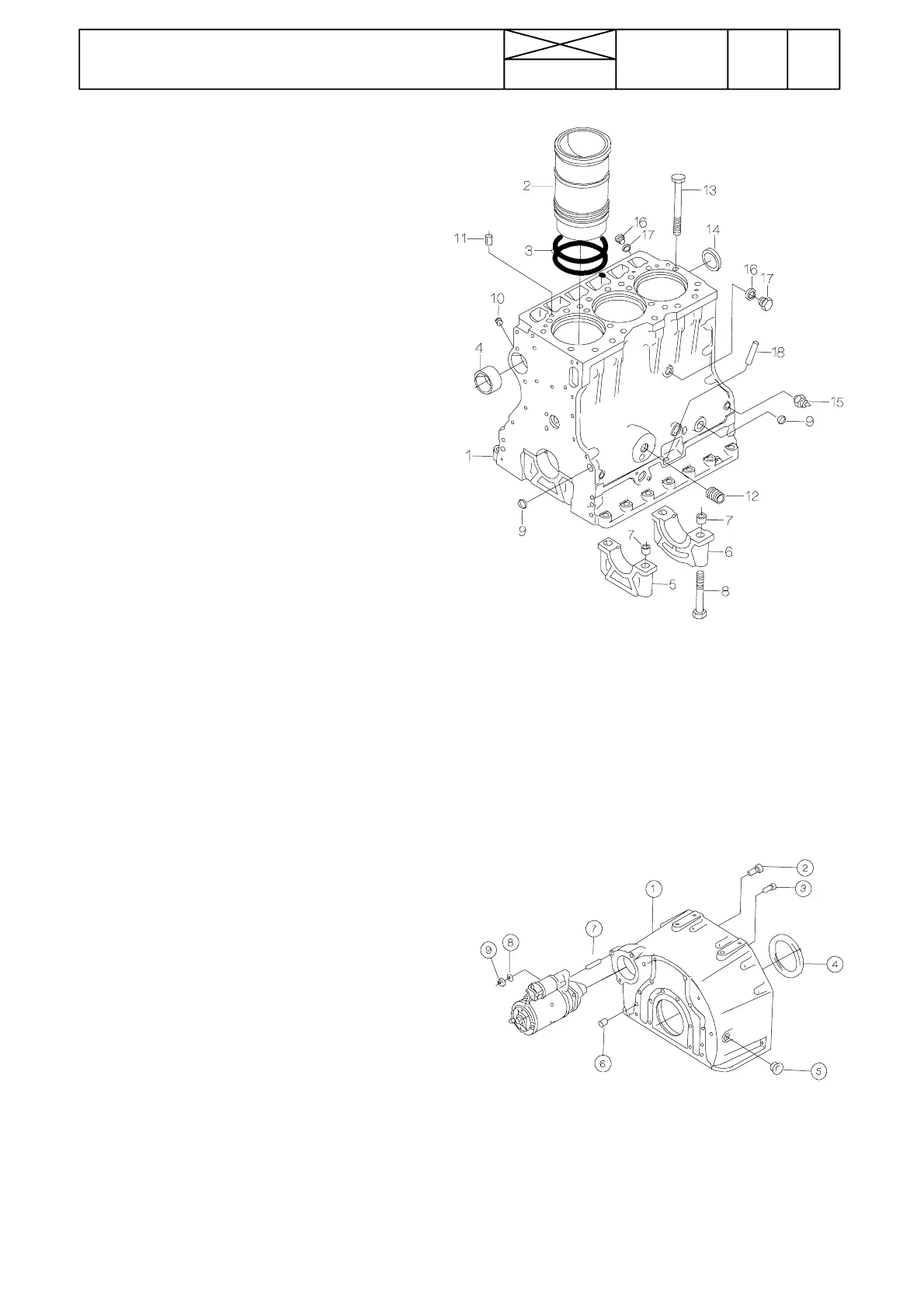
Cylinder block
Figure 210 4
1. Cylinder block
2. Cylinder liner
3. O --- r in g
4. Bearing sleeve
5. Bearing cap
6. Bearing cap with thrust bearing
7. Guide sleeve
8. Bolt
9. Plug
10. Threaded plug
11. Guide pin
12. Threaded connection
13. Cylinder head bolt
14. Plug (camshaft end)
15. Pressure sender unit
16. Sealing ring
17. Plug
18. Pipe for oil dipstick
The cylinder block is the main body o f the engine, to which
other engine parts are attached. The cylinder liners are so
calledwet liners,which means that the coolant is in direct con-
tact with the outer surface of the liners. The seal between the
cylinder liner lower part and the cylinder block is achieved by
two O ---rings (3), which are fitted in grooves in the liner. The
upper part is sealed by the cylinder head gasket. The distance
between the cylinder liner flange and the face of the cylinder
block plays a major role in sealing the upper part. Bear this in
mind when fitting the cylinder liner.
Flywheel housing
Figure 210 5
1. Flywheel housing
2. Bolt M12x35
3. Socket head bolt M10x30
4. Crankshaft oil seal
5. Rubber plug
6. Tubular pin
7. Screw stud 10x25
8. Washer
9. Nut M10
The flywheel housing is fitted to the re ar end of the cylinder
block. The starter motor and the crankshaft rear oil seal are
also fitted in the flywheel housing. There is also a hole in the
flywheel housing for inserting a tool in order to crank the
engine. The return oil flow from the engine lubricating system
is channelled through the flywheel housing.
The camshaft is located in the cylinder block. The camshaft
front bearing location is provided with a separate bearing
sleeve (4). The remaining bearing locations are machined
directly in the cylinder block. The drilling for the camshaft rear
end is covered with a plug.
Thereis space on bothsides of therearmainbearing forguide
bearing shims (the camshaft thrust bearing).
The lower face of the flywheel housing fits up against the oil
sump and its front face against the cylinder block. This has to
be taken intoaccountwhen fitting the flywheel housing,which
is guided partly by the guide pin (6).