35
Model Code Page
21. Engine
205-- 555 210 15
1. 12. 1986
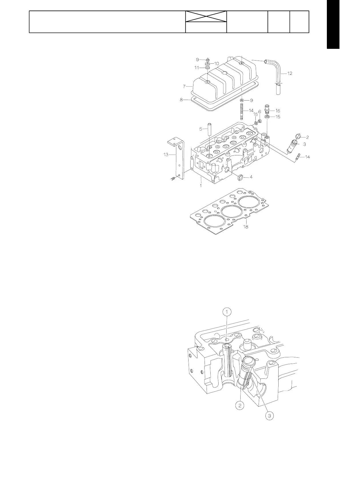
Cylinder head
Figure 210 6
1. Cylinder head
2. O --- r in g
3. Sleeve for injector
4. Plug
5. Valve guide
6. Plug
7. Valve cover
8. Gasket
9. Nut
10. Washer
11. Rubber seal
12. Breather hose
13. Lifting bracket
14. Screw stud
15. Sealing ring
16. Hose coupling
17. Bolt
18. Cylinder head gasket
The cylinder head is made of cast iron, and each cylinder has
its own inlet port and common exhaust port. The stiffness and
even spread of attaching bolts give a good seal for the cylin-
der head gasket. The directed flow of the cool ant ensuresthat
the valve seats are effectively.
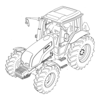
Cross---section of cylinder head
1. Valve guide
2. Injector sleeve
3. O --- r in g se a ls
The inlet and exhaust valve guides (1) are identical and can
be interchanged. The injectors are surrounded by replace-
able copper sleeves (2) which are in contact with the coolant,
thus the injectors are effectively cooled.