36
Model Code Page
21. Engine
205-- 555 210 16
1. 12. 1986
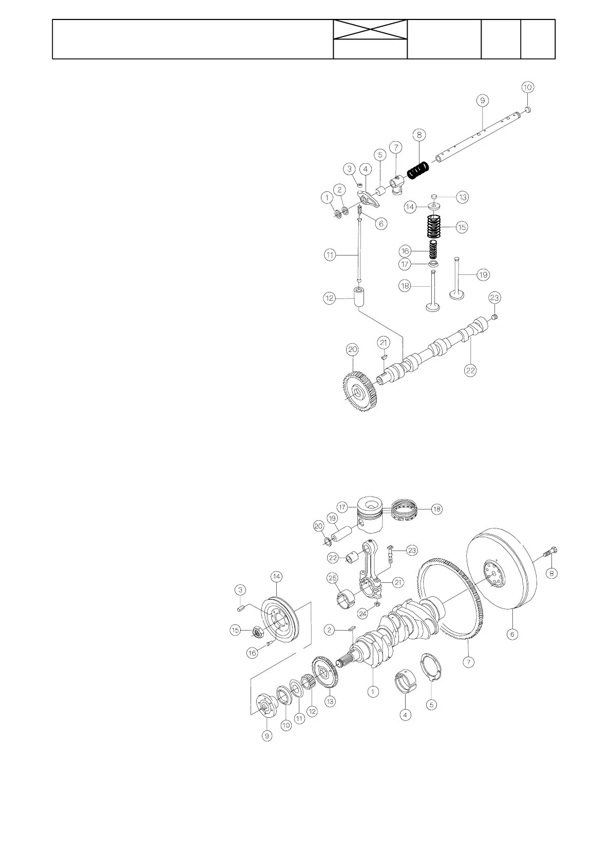
Valve mechanism
1. Circlip
2. Shim
3. Nut
4. Rocker arm
5. Bearing sleeve
6. Adjusting screw
7. Holder
8. Spring
9. Shaft
10. Plug
11. Pushrod
12. Tappet
13. Valve keepers
14. Spring guide
15. Valve spring
16. Valve spring
17. Spring guide
18. Exhaust valve
19. Inlet valve
20. Gear wheel
21. Key
22. Camshaft
23. Threaded plug
The valve mechanism is operated by the camshaft (22) which
is located in the cylinder block. The drive is transferred with
the help of tappets(12) and pushrods (11). The camshaft gear
wheel (20) is fitted with a press fit and fixed with a key (21).
Each bearings is lubricated by the force feed lubrication sys-
tem through drilled oilways in the camshaft.
Crank mechanism
1. Crankshaft
2. Key
3. Cylindrical pin
4. Main bearing
5. Thrust bearing
6. Flywheel
7. Ring gear
8. Bolt
9. Hub
10. Shaft seal boot
11. Deflector ring
12. Gear wheel
13. Gear wheel
14. V ---belt pulley
15. Nut
16. Socket head bolt M8x16
17. Piston
18. Piston rings
19. Piston pin
20. Retaining ring
21. Connecting rod
22. Bearing bushing
23 Bolt
24. Nut
25. Crankshaft bearing
The crankshaft (1) is forged from chrome alloy special steel
and is inducti on hardened at the bearing and sealing sur-
faces. Gear wheels (12 and 13) are located at the front end of
the crankshaft. They are fitted with a press fit, and drive the
idler wheel and oil pump. In addition, the front end of the
cr a nk ---
shaft has splines for the hub (9) of the V---belt pulley (14). An
oil deflector ring (11) is fitted between the hub and the gear
wheel, and a dust shield (10)is fitted to the hub in order to seal
the shaft.