37
Model Code Page
21. Engine
205-- 555 210 17
1. 12. 1986
The flywheel (6) is fitted to the rear end of the crankshaft. The
ring gear (7) is fitted to the flywheel with a press fit. The forged
connecting rod has an I ---shaped cross---section. The bear-
ing location at the bottom end of the connecting rod is split,
and the bearing cap is secured by two special bolts (23) and
nuts (24). The upper end of the rod has a fixed bearing loca-
tion, in which the piston pin bearing bushing (22) is fitted with
apressfit.
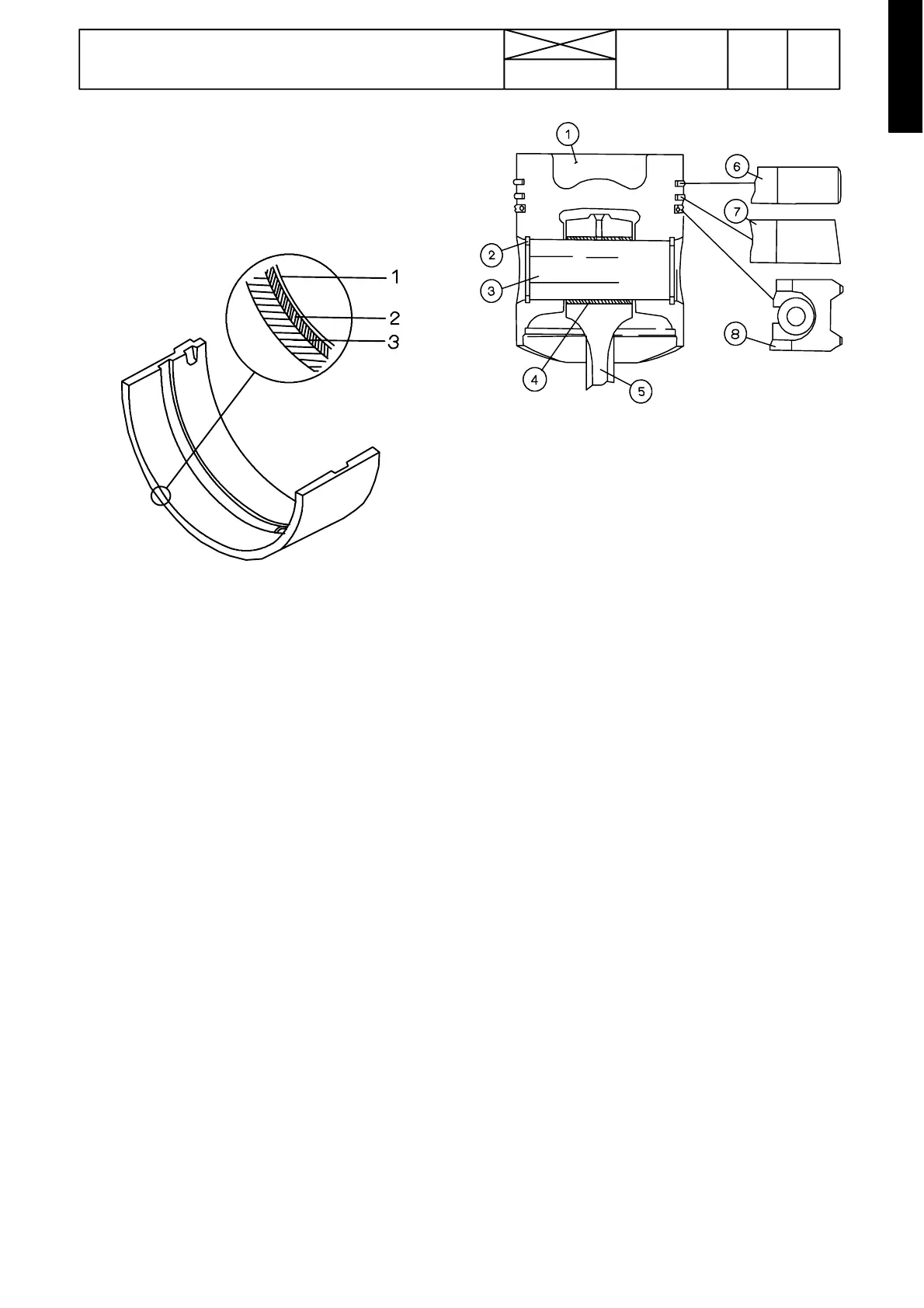
Bearing shell
1. Indium---lead alloy
2. Lead---bronze
3. Steel shell
The crankshaft has four main bearings, one on either side of
each cylinder. The thrust bearing is located on either side of
the rear main bearing journal. The main and big---end bear-
ings are three---layer bearings, which have a tough lead
bronze alloy, with good heat dissipating properties, inside the
steel shell. The actual sliding surface is covered by a layer of
indium---lead, which makes the running---in period easier.
Piston
1. Combustion chamber
2. Circlip
3. Piston pin
4. Bearing bushing
5. Connecting rod
6. Chromed compression ring
7. Compression ring
8. Spring loaded oil control ring chromed slide surfaces
The pistonis made of an eutectic aluminium alloy.In theupper
part of the piston there is a combustion chamber (1). The
shape of the chamber is intended to maximise the mixture of
air and fuel. The number of piston rings is three, of which the
upper (6) has a barrel face, chromed slide surface. The sec-
ond compression ring (7) is tapered at an angle of 1,5˚,and
the third ring is a spring loaded oil control ring (8). The piston
pin (3) has a close tolerance in the piston and a floating fit in
the connecting rod.