HP
ITEM
GRAPHICS
CODE
※:Optional according to
DESCRIPTON
REMARKS
ITEM
GRAPHICS
CODE
DESCRIPTON
REMARKS
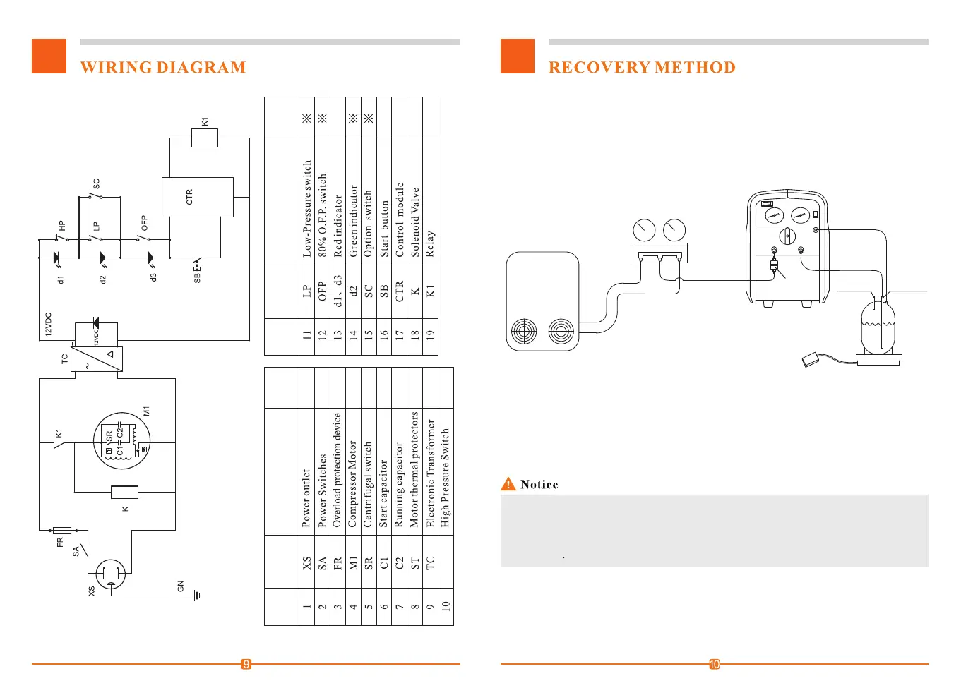
1. Turn the Switch to position "1".
2. Correctly and firmly connect the pipes.(See Connection Drawing)
3. Connect the unit to the right power supply(as shown on the Name Plate), turn the
power on(I), and the BYPASS switch to MANUAL.
4. Hit the START button to start the unit.
5. Open the valve of the refrigerant tank.
6. Open the liquid valve of the manifold gauge.
7. Slowly turn the Switch to position "2" for faster recovery.
8. Turn the BYPASS switch to "AUTO" so that the unit will automatically stop
when finished.
Purge operation now.
9. When liquid recovery is finished, turn the Switch to position "2" for faster recovery.
10. The unit will automatically stop when recovery is finished, please do the
HVAC Syetem
Liquid
Vapor
Manifold
gauge set
Input
Filter
Scale
Tank
Liquid valve
Vapor valve
Output
O.F.P. cable
6 7
ST
① If compressor impact occurs, turn the Switch to position "1" till the impact stops.
② If the power goes off when the unit is working, and the unit cannot restart, you can
turn the Switch 2 rounds and stop at position "1", turn the power on and hit the Start
button to start the unit.