The VAMP 221 is a modular arc protection system designed to safeguard electrical distribution systems from arc faults, minimizing personal injury and material/production losses. It is suitable for both low and medium voltage switchgear, and can be installed in new or existing systems.
Function Description
The VAMP 221 system operates with an impressive 7-millisecond operating time, providing rapid protection. It offers accurate location of arc faults and supports four selective protection zones. The system includes comprehensive self-supervision of all components and cabling, ensuring reliable operation.
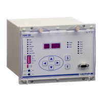
Central Unit VAMP 221:
The central unit is the core of the system, providing:
- Overcurrent and Arc Stage: Features a 3-phase overcurrent and arc stage, or alternatively, a 2-phase overcurrent, earth-fault, and arc stage.
- Circuit Breaker Failure Protection (CBFP): Includes a CBFP stage for enhanced protection.
- Optional Trip Criteria: Supports various trip criteria such as light and overcurrent (I>&L>), overcurrent only (I0>&L>), or light only (L>).
- Tripping Groups: Offers two mutually independent tripping groups and four output trip relays.
- Protection Zones: Manages four distinct protection zones.
- BI/O Bus: Utilizes a BI/O bus for light and overcurrent information exchange.
- Indications: Provides status, fault, and trip indications.
- Scalability: Accommodates up to 16 I/O units.
- Self-Supervision: Continuously monitors the system for internal faults.
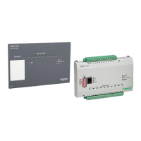
I/O Units (VAM 10L, VAM 3L, VAM 3LX, VAM 4C):
These units connect sensors to the central unit and offer:
- Sensor Accommodation: VAM 10L supports up to 10 arc sensors, VAM 3L and VAM 3LX support up to 3 fibre loops (VAM 3LX includes sensitivity adjustment). VAM 4C accommodates up to 3 current transformers.
- Output Trip Relay: Each I/O unit is equipped with one output trip relay.
- Active Sensor Indication: Provides indication of an active sensor.
- Protection Zone Addressing: Supports protection zone addresses (max. 4 zones).
- Flexible Installation: Allows free placement within the switchgear and uses factory-made modular or instrumentation cables for intra-unit cabling.
- Portable Sensor Connection: VAM 10L, 3L, and 3LX units include a connection for a portable arc sensor.
Arc Sensors (VA 1 DA, VA 1 EH, ARC-SLx, VA 1 DP):
These sensors detect light information and transfer it to the I/O units.
- VA 1 DA & VA 1 EH: Transform strong light into a current signal, transferred to the central unit via VAM 10L. Available in 6m and 20m cable lengths. They are cost-effective, easy to install/repair, and self-supervised. VA 1 EH can be installed in a tube to monitor a specific zone.
- ARC-SLx: Durable glass fibre sensors available in lengths from 10m to 35m. The first 2.5m are insulated against light. They are ideal for monitoring multiple compartments in low voltage switchgear and are self-supervised.
- VA 1 DP (Portable): Improves personal safety when working with live switchgear. It connects to the nearest light I/O unit via a snap-in connector with a 5m cable and can be attached to a technician's pocket.
Multiplying Relays (VAR 4CE, VAMP 4R):
- VAR 4CE: Provides four potential-free electromechanical output trip relays with an operating time of 5ms. It can be controlled by an I/O unit trip relay or DO output.
- VAMP 4R: Offers eight potential-free contacts (4 normally open, 4 normally closed) for outgoing trip signals, divided into two groups.
Modular Cable VX001:
Used for connecting I/O and central units. It features quick-disconnect connectors and is available in various lengths (1m to 50m). The total cable length from the central unit to the furthest I/O unit should not exceed 100m.
Important Technical Specifications
- System Operating Time: 7 milliseconds.
- Protection Zones: Four selective protection zones.
- Current Measuring: Phase current (L1/L3: 0.5-6xIn, L2/I0: 0.05-5xIn) and earth-fault current measuring.
- EMC Compliance: Complies with the latest electromagnetic compliance standards for protective relays.
- Auxiliary Power Supply (VAMP 221): 48-265 V ac/dc, 110/120/220/240 VAC 50/60Hz, 48/60/110/125/220 V dc. Power consumption < 7 W (normal mode), < 10 W (output relays activated).
- Auxiliary Power Supply (I/O Units): 24 V dc. Power consumption < 1 W (normal mode), < 1.5 W (output relays activated).
- Auxiliary Power Supply (VAR 4CE): 24 V dc. Power consumption < 0.5 W (normal mode), < 4.5 W (output relays activated).
- Auxiliary Power Supply (Arc Sensors): 12 V dc (from I/O unit). Power consumption < 35 mW (normal mode), < 450 mW (activated).
- Trip Contacts (VAMP 221): 4 closing contacts (T1-T4), rated 250 V ac/dc, continuous withstand 5 A, make and carry 30 A (0.5s) / 15 A (3s).
- Trip Contacts (I/O Units): 1 closing contact (T1), rated 250 V ac/dc, continuous withstand 5 A, make and carry 30 A (0.5s) / 15 A (3s).
- Alarm Contacts (VAMP 221): 2 normally open, 1 normally closed (self-supervision relay).
- Communication Bus: RS485 (15 kV) for information and self-supervision. RJ45 electrical connection. Max 16 I/O units, 3 central units.
- Local Serial Communication: RS 232 (9600 kb/s for software updates).
- Unbalance Alarm: Detects significant current unbalance (90% deviation) with a 10-second operating time.
- Casing (VAMP 221): IP20, 208x155x223 mm, 4.2 kg.
- Casing (I/O Units, VAMP 4R): IP21, 157x92x25 mm, 0.52 kg.
- Casing (VAR 4CE): IP21, 140x90x60 mm, 0.52 kg.
- Casing (Arc Sensors): IP21.
Usage Features
- User Interface: The central unit features a display, status indicators, buttons, and programming switches for control and configuration.
- Menu Navigation: Intuitive navigation using up/down/left/right arrow keys, SET (S) button to activate functions, and ENTER (E) button to execute.
- System Status Indications: LEDs for RUN, INSTALL, INFO, TEMP SET, TEMP, CURRENT, ERRORCODE, POWER, COM, ERROR, and trip indications (Trip1-4, I>int, I>ext).
- Fault Memory: Stores up to three latest fault codes, which can be read and reset manually or automatically after two hours.
- Overcurrent Setting: Adjustable via potentiometers in CURRENT mode, with settings expressed as multiples of the secondary rated current.
- System Configuration: Automatic system configuration after connecting units and applying supply voltage. Configuration can be checked in INFO mode.
- Programming Switches: DIP switches on central and I/O units define trip relay matrix, current transformer secondary current, overcurrent settings, trip relay latch, arc trip criteria (light only or light + current), CBFP operating speed, and unit addresses/zones.
Maintenance Features
- Self-Supervision: Continuous monitoring of all system components and cables. Detects internal faults and generates fault codes (e.g., configuration fault, damaged I/O unit, communication fault, unbalance fault).
- Fault Code Diagnostics: Fault codes provide specific information to help locate faulty components (e.g., sensor connections, modular cables, supply voltage, current transformers).
- Testing Procedures: Detailed commissioning instructions for systematic testing, including activating each sensor, verifying tripping with current criteria, and checking selectivity of protection zones.
- Periodic Commissioning: Recommended every five years or as per local regulations, with a testing protocol provided for documentation.
- Software Updates: Communication port available for loading software updates.
- Modular Design: Facilitates easy replacement of individual components in case of damage.
- Troubleshooting Guide: The manual provides comprehensive troubleshooting steps for various alarms and fault codes.