Seismic Detectors Application Guide
GMXS5 external test transmitters are installed externally on walls C and E in position 3 and 3. In
this example, the floor, ceiling, and rear walls are not externally accessible and so the detectors in
these areas are tested by using GMXS1 internal test transmitters.
Practical sensitivity and noise checks should always be performed before the installa-
tion is completed.
Exact detection range and capabilities can only be determined by practical tests on
site.
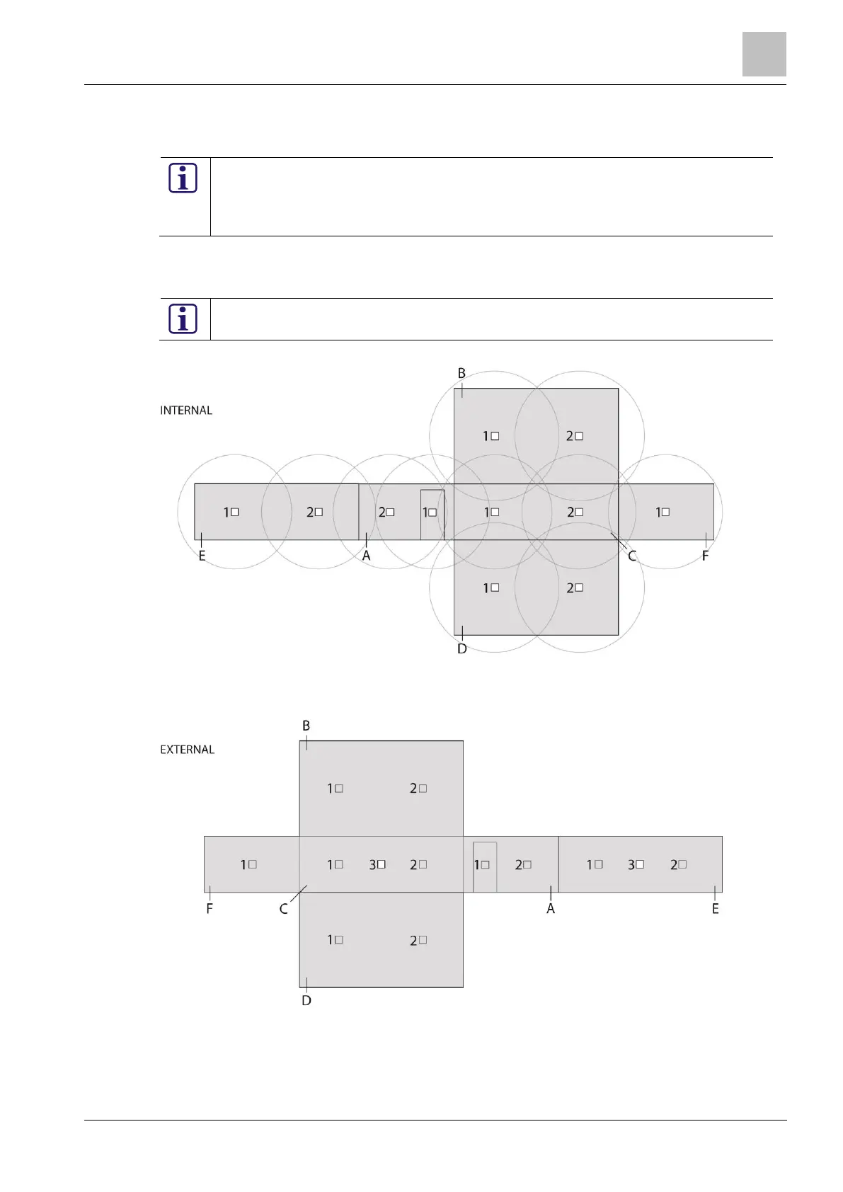
In Figure 6-11 and Figure 6-12, the detector layout is shown for the same application.
Figure 6-11 shows the positioning of the internally installed detectors with the associated operating
radius for each detector.
Using a scale drawing of the room to be protected and adding the operating radius is a
good method of verifying a system design.
Figure 6-11: Example 2 - detectors inside vault
Figure 6-12 shows the GMXS5 external test transmitters mounted on the exterior of the vault at C3
& E3.
Figure 6-12: Example 2 - detector layout and external devices
Figure 6-13 shows the detector location and the operating radius for each detector. This is an ex-
ample to demonstrate that each surface of the vault has comprehensive detection coverage. The

 Loading...

