OPERATION
For welding with solid wire, use the gas setup described
on previous page, and connect ground wire and clamp
according to diagram "A" at right.
For welding with ux-core wire, gas is not necessary.
Connect ground wire and clamp according to diagram
"B" at right.
1. Attach ground clamp to work piece. Make sure teeth on clamp make a good, solid electrical
connection through paint, rust, etc.
2. Set MIN/MAX and 1/2 Switches according to metal specication.
3. Make sure power switch is "OFF" then plug power cord into electrical outlet.
4. Remove nozzle cover and contact tip from welding torch and pull the hose.
5. Ensure that the welding tongs holding the rod are not contacting any grounded objects, then turn
the conversion switch to voltage position (the same as input voltage). The green power lamp will
light.
6. Turn power switch to "ON". Press and hold trigger until 30mm of wire comes out. Release trigger.
7. Shut off power and replace nozzle and contact tip, ensuring that wire extends through contact tip.
8. Turn power back on, press trigger intermittently to adjust wire feed speed using wire speed knob.
9. Orient yourself on the area to be welded, and the place the face shield over your face.
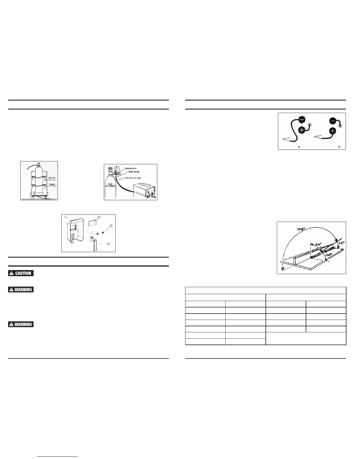
10. While holding trigger, stroke the wire against the area to be welded to ignite the arc.
11. Once arc is ignited, tilt the electrode wire forward at an angle of approximately 35˚. See diagram.
12. When the weld is complete, lift the electrode away from any grounded object, remove face shield,
and turn power switch to "OFF".
ASSEMBLY AND SET UP (CONTINUED)
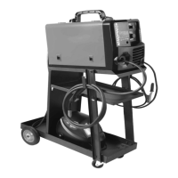
Gas Cylinder Installation
The welder has a platform on the rear to accommodate a small gas cylinder. (If you plan to use a
large cylinder, chain it to a wall or bench, or obtain a cart designed specically for the cylinder).
1. Secure the small cylinder to the cart using the straps on the cart.
2. Clean the threads on the gas outlet valve, and open valve briey to blow any debris away from the
inside of the valve tting.
3. Attach regulator to the gas valve on top of the cylinder.
4. Attach welder gas line to hose barb output on regulator and secure in place with hose clamp.
5. Check all tting for leaks by opening gas cylinder valve and regulator valve.
6. Close all valves when not in use.
Assemble the face shield according to the diagram below:
OPERATION AND MAINTENANCE
If the welder begins operating improperly, stop working at once and
determine the source of the problem. Any necessary repairs must be
performed by a qualied service technician.
Before performing any maintenance or repairs, turn power to OFF and
unplug unit from power source.
Keep welder unit clean. Open side door and using low-pressure, clean, dry compressed air, remove
dust and dirt from internal parts, electrical contacts, inside of housing and all ventilation ports.
After cleaning, check to make sure there are no loose parts or ttings. If any loose parts are found,
tighten as necessary.
Be sure all cables and electrical contacts are connected rmly. Loose
connections can cause arcing which can hurt your eyes or start a re.
Arcing while in contact with your body can cause severe injury or death.
12 1313
Current output chart
MIG-175 MIG-135
Switch Position Output Amperage Switch Position Output Amperage
1 30A MIN-1 30A
2 50A MAX-1 50A
3 75A MIN-2 70A
4 95A MAX-2 90A
5 110A
6 135A
 Loading...