Do you have a question about the Varian ProStar 325 and is the answer not in the manual?
Guidance on navigating and understanding the manual's structure and content.
Locating specific details using the table of contents and section structure.
Detailed list of the detector's advanced optical, electronic, and modular capabilities.
Explanation of the detector's core functionality, operation modes, and configurations.
Overview of the Verify software and its suite of performance verification tests.
Critical information on electrical hazards, lamp safety, panel access, and general precautions.
Varian's approach to servicing, including warranty, support, and repair policies.
Explanation of warning and caution symbols used throughout the manual.
A checklist to ensure all site preparations and requirements are met before installation.
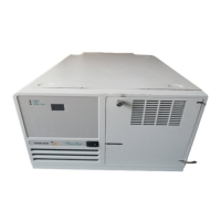
Specifications for detector weight and shipping dimensions, with handling safety warnings.
Recommended laboratory conditions, temperature, humidity, and suitability for the detector.
Guidelines for selecting and preparing a suitable workbench for system installation.
Details on power supply requirements, grounding, and mains voltage compatibility.
Information on fuse types, ratings, and procedures for replacement.
Details on rear panel connectors for communication, sync signals, and power.
Procedures for handling equipment upon delivery, including insurance and damage inspection.
Requirements and setup for connecting the detector to a computer system via Ethernet.
Steps for configuring the PC, including installing specific software and display settings.
Information on the scope and availability of operator training provided during installation.
Overview of the installation and maintenance procedures for the ProStar325 detector.
Steps and requirements that must be met before the detector can be installed.
Estimated time breakdown for standard detector installation, testing, and handover.
Confirmation steps and safety considerations before commencing the installation process.
A guide for CSRs to ensure all installation steps are completed correctly.
Procedure for installing a door cap on the ProStar 325 module.
Instructions on how to attach or detach the module door covering flowcell connections.
Detailed steps for installing the Verify software and related applications on the host computer.
Configuration steps for establishing an Ethernet connection between the detector and PC.
Information on controlling the detector using an infrared (IrDA) link with a handheld PC.
Details on cabling connections for the monitor, printer, and detector to the PC.
Pin designations and usage for synchronizing multiple instruments in an HPLC system.
Procedures for connecting the detector to the mains power supply, including safety checks.
Detailed instructions on how to check and replace fuses, including safety warnings.
Steps to power on the detector and initiate its start-up routine, including troubleshooting.
Explanation of the dual-color LEDs on the front panel indicating detector status.
Description of the six operational states the detector can be in and factors influencing transitions.
Procedures for running performance tests using the Verify application to confirm specifications.
Details on flowcell types, removal, re-installation, tubing, storage, and cleaning.
Function and installation of the back pressure restrictor to prevent outgassing and bubbles.
Explanation of how to calibrate for extended absorbance range using path length ratios.
Information on factory-aligned source lamps and procedures for replacement and calibration.
General cleaning instructions for the exterior surfaces of the detector.
Troubleshooting guide for identifying and resolving issues causing excessive noise or drift.
Description of the detector's main power supply modules and their voltage outputs.
Overview of the main processor PWB, its functions, and component-level repair considerations.
The sequence of operations performed by the detector when it is powered up.
Explanation of front panel LEDs and seven-segment displays indicating detector status.
How to use the 16-position switch to select and run diagnostic routines for the instrument.
Function of the pre-amplifier PWB in converting photodiode signals for processing.
Description of the LED/IrDA display PWB and its role in indicating detector status.
Detailed instructions for safely removing and replacing internal electronic components.
Description of the optics module's components and its role in forming sample and reference beams.
General safety precautions and detailed steps for removing and replacing optical components.
Steps for installing the Vis lamp upgrade kit, including component identification.
Procedure for optimizing the light throughput of the Vis lamp using diagnostic software.
How to execute instrument performance tests after installation or component replacement.
List of part numbers for various detector covers and panel assemblies.
Part numbers for electronic components such as PWBs and looms.
Part numbers for optical assemblies, including lamps and complete optics modules.
Part numbers for upgrade kits, such as the Vis lamp field upgrade.
Part numbers for essential system cables, including Ethernet crossover and network cables.
Part numbers for miscellaneous items like regulators, fittings, software, and manuals.
Explanation of the automatic self-tests performed by the detector upon power-up.
The step-by-step process the detector follows during its power-up and initialization routine.
Description of front panel LEDs and their color coding to indicate detector status.
How to use the diagnostic switch to run specific tests on the detector's Printed Wiring Boards.
Instructions for using the diagnostics CD and the Diagnostic.exe application for system verification.
How to view spectrum traces and instrument status using the main display.
Procedures for building, modifying, and downloading methods for detector operation.
Accessing detailed status information about the detector, lamps, and connectivity.
Overview of various diagnostic sub-pages for detailed system checks and parameter adjustments.
Steps to establish communication between the diagnostic software and the detector.
Procedures for calibrating the detector's optical and wavelength parameters.
| Brand | Varian |
|---|---|
| Model | ProStar 325 |
| Category | Security Sensors |
| Language | English |