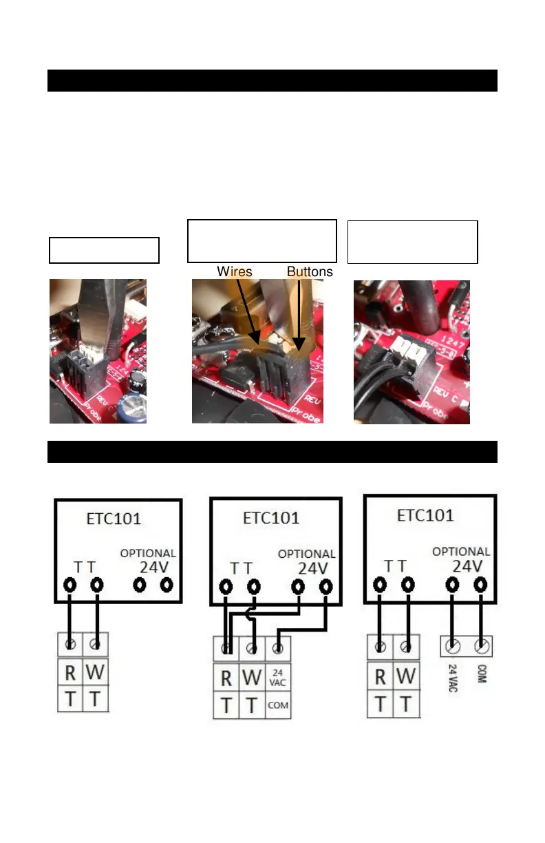
13
Thermostat Diagram 4
Inserting the probe wires into the press release connector
4.A – Position tool on top of white buttons
4.B – Push Down on buttons and push wires Down into holes in top of
connector (This can also be done one side at a time)
4.C – Tug on each wire to make sure they are secure
Wires Buttons
Thermostat Diagram 5
Typical Wiring Wiring with optional 24V, if needed
For TPI Thermostats, the 24V Power is required.
4.B Buttons down,
Wires pushed down
4.C Buttons up,
Wires tight