Turn on the power at fuse or circuit box.
Turn off the power at fuse or circuit box
Installation Steps
1. Unscrew the end cap (D) and remove the rubber pad (E) from mounting strap unit (A).
2. Attach the mounting strap unit (A) to the outlet box by using two mounting screws (B). Adjust the length of the
preinstalled threaded pipe if necessary.
3. Pull out the source wires from the outlet box. Make wire connections using wire connectors (C) as follows:
• Connect the hot wire (usually black insulation) from the fixture to the black wire from the power source.
• Connect the neutral wire (usually white insulation) from the fixture to the white wire from the power source.
• Attach the fixture grounding wire (usually green with the insulation or bare wire) to the mounting strap unit (A)
with the green grounding screw. Then, depending on local code, connect it to the house grounding wire with
the wire connector (C).
Carefully put all of the wires back into the outlet box.
4. Attach the backplate of the fixture to the mounting strap unit (A) by inserting the threaded pipe, then secure it with
the rubber pad (E) and end cap (D).
Note: With silicone caulking compound, caulk completely around where the backplate meets with the wall
surface to prevent water from seeping into the outlet box.
5. Install the bulb (not included). See relamping label at socket area or packaging for maximum wattage allowed.
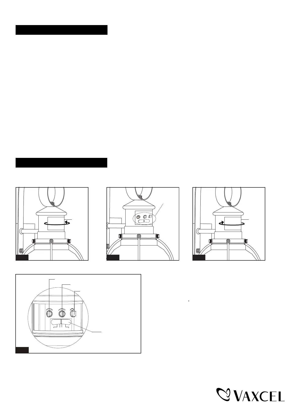
The Position of Control Panel
Step 1: Rotate the sensor lens from left side to right side
to show the adjustable knobs and slide switch.
(See Fig.1)
Step 2: Adjust time
by knobs and choose the mode you want by
slide switch. (See Fig.2 and Fig A).
Step 3: Restore the sensor lens to original position.
(See Fig.3)
low level brightness and sensitivity
Sensor
Lens
Fig.1
Sensor
Lens
Fig.3
View Fig.A
Fig.2
Page 2 / 5
“Time” Knob
“Sens” Knob
Slide Switch
“Low Level” Knob
Time Low Level
Sens
Fig.A
Test
3H
6H
0
210317