3
f
i
e
e
g
h
f
ca 5°
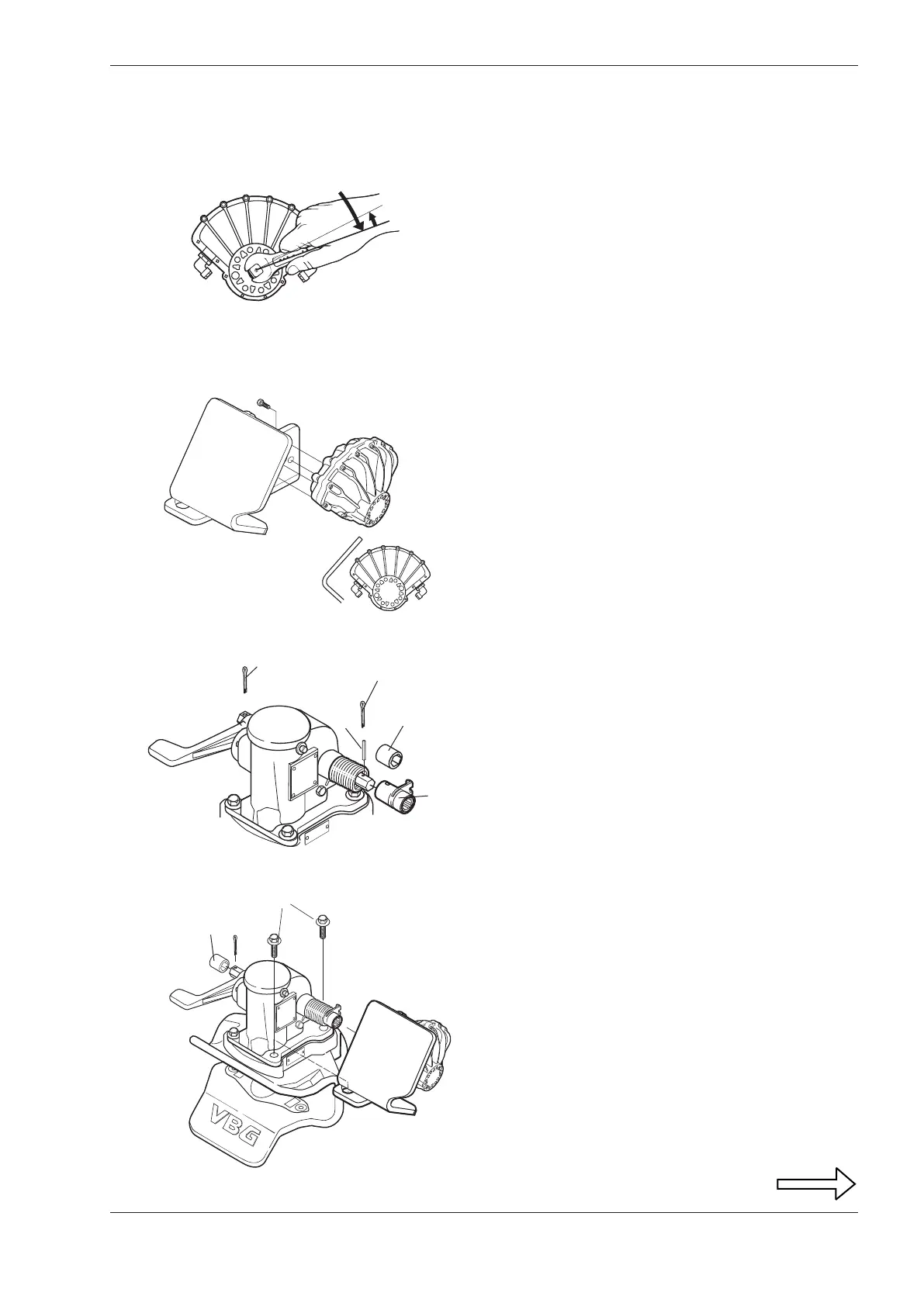
Mounting of a power actuator
If the coupling is to be equipped with a power actuator,
follow the directions below.
Mounting the power actuator on the
coupling
• Remove the two split pins (e) and the right hand
bushing (f).
• Mount the adapter (g) on the hexagonal shaft and fi t
with the roll pin (h) through the hole in the adapter.
• Tap the hexagonal shaft to the left and lock the hook
on the adapter into the hook on the spring.
• Assemble the bushing (f) on the left side and refi t the
split pin.
• Remove the two screws on the right side of the
mechanism (i).
• Place the bracket and actuator on the coupling. Lock
the bracket securely with the two long M12 screws
which accompanied the power actuator unit.
Tightening torque M12 quality 8.8 (dry): 90 Nm.
Mounting of the actuator on the bracket
• Turn the shaft on the actuator clockwise until it can go
no further and then turn it back approx. 5º.
• Bolt the actuator tightly onto the bracket with the four
screws. Tightening torque M8 quality 8.8 (dry): 25 Nm.