4
Ø 6
Ø 8
4
Ø 6
2
1
Alt. A
Alt. B
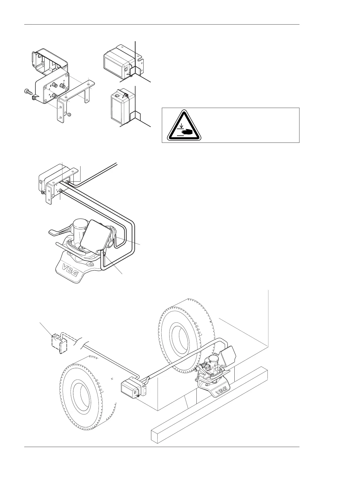
Mounting of the control box
• Mount the control box close to the coupling so that the
operation of the coupling can be watched. The control
box must be positioned so that it is well protected from
vibration, impact, dirt and ice formation.
Mount the control box as shown in Alt. A or B.
NOTE! Electrically controlled control boxes are not
permitted.
Fitting the Pipes
• Turn the handle on the control box to service position
according to “Service position control box” on page
6.
• Connect the supply line to the control box output
(marked 1).
• Connect the other 2 pipes to the control box outputs
(2 and 4). Fit the protective cover.
• Connect the pipe from output 4 on the control box to
the front output of the actuator. The pipe from output 2
is connected to the rear output of the actuator.
• Connect the supply line to the vehicle´s auxiliary air
system. Working pressure 8 bar.
Maximum pressure 10 bar.
Always follow the truck manufacturer’s body building
instructions.
NOTE! Do not connect to the braking system.
The vehicle´s auxiliary
air system
Warning!
Never put your fi ngers in the coup-
ling mouth because of the danger
of them being crushed.