5
+
–
20
40
60
80
100
120
approx 1 mm
Brown
Black
Blue
Inductive
sensor
g
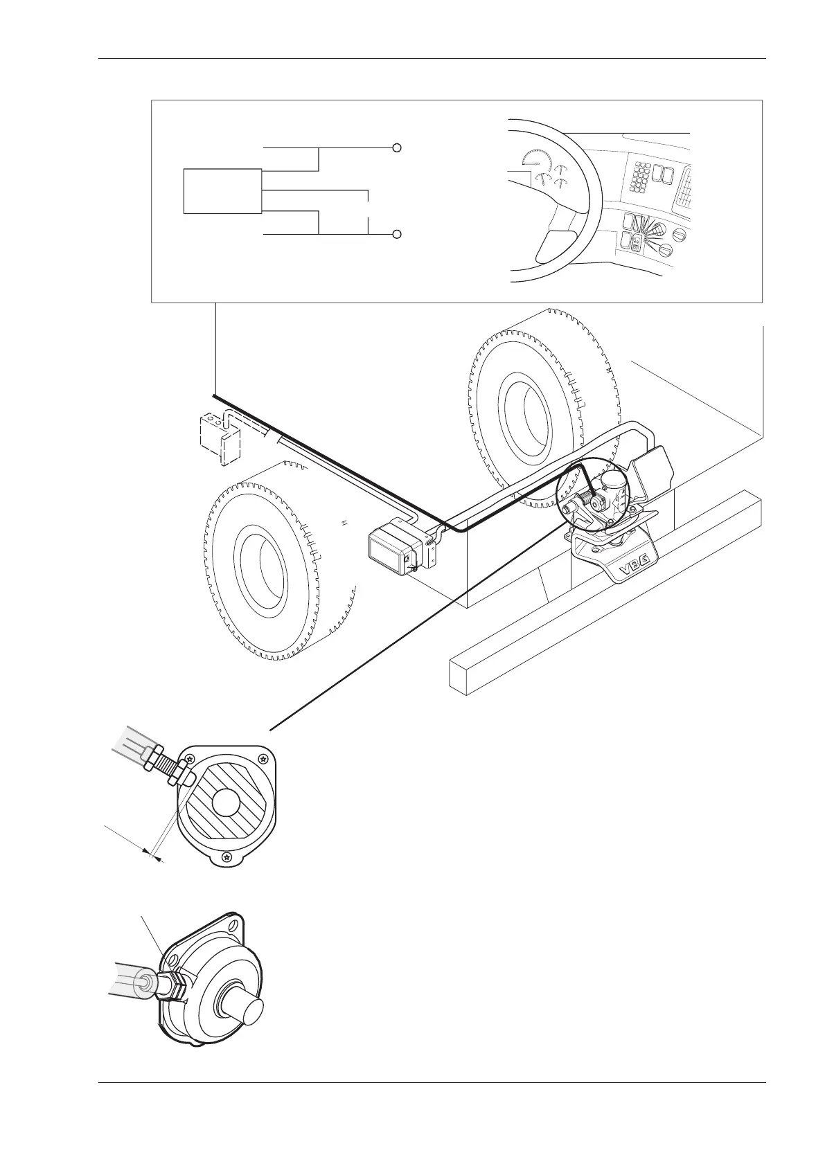
Signal
Signal: red and green lamp, (24 V max. 2 W)
Mounting of inductive sensor
• Change the cover of the original lock indicator for
the cover modifi ed for the inductive sensor. Open the
coupling so that the indicator pin is out. Wind the induc-
tive sensor in until it touches the indicator pin. Wind the
inductive sensor back one turn (the distance between
the indicator pin and the inductive sensor should now
be approximately 1 mm).
Tighten the nuts (g), tightening torque max. 2 Nm.
• If VBG’s Indicator kit (part no. 09-099200) is used –
connect the inductive sensor according to the mounting
instructions. Otherwise connect the inductive sensor to
the vehicle’s electrical system (24 V). See wiring diagram
above. Follow the truck manufacturer’s instructions.
• When the coupling is closed and secured a green
lamp in the cab should light up.
• When the coupling is open, a red lamp in the cab
should light up. If the green lamp comes on when the
coupling is open, adjust the gap between the sensor
and lock pin so that the red lamp comes on.