Do you have a question about the Veco Climma Fancoil EVA Series and is the answer not in the manual?
| Brand | Veco |
|---|---|
| Model | Climma Fancoil EVA Series |
| Category | Air Conditioner |
| Language | English |
Details the refrigerant circuit transfer of heat from ambient air to sea water during cooling.
Key elements for choosing unit installation position: accessibility, space, connections, and duct routing.
Unit must be in the conditioned room; conditioned air piped to grills via ducts.
Fastening the thermostat bulb to the air exchanger, separated from it, or in the room.
Fixing using provided clamps, suggesting anti-vibrant for cabins and careful cable handling.
Instructions for fixing the Fancoil FC model to the ground.
Fixing FCC models using pre-existing holes in the fancoil structure.
Discharging condensation water generated by humidity into bilge or tank, then to sea.
Importance of the air filter for cleaning air before it enters the heat exchanger to prevent obstruction.
Covers aspiration, air circulation, air ducts, and specific fan coil model connections for optimal airflow.
Details one outlet, two outlet systems, and duct specifications for air distribution.
Contains electrical connections for grid, compressor, panel, pump, and probe.
Setting and controlling functions like cooling, heating, temperature, and fan speed.
Technical specifications and installation directions for the VEGA MKII digital control panel.
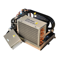
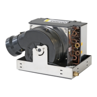
Details configurations of Climma fancoils: EV (with EH), FC, and FCV.
Check supply correspondence and connect electrical box to mains via a suitable circuit breaker.
Explains pre-set electrical box configuration and settings for replacement parts or board changes.
Informs about the power fuse included in the board and reference for its value.
Explains the meaning of various warning lights (LEDs) indicating system status on the PCB.
Details PCB connections: RS 485 Modbus, Change Over, ALM, and various connectors.
Fault detection must be performed by qualified technicians following safety rules.
Recommends regular maintenance: filter cleaning, drain pipe checks, and battery replacement.
Checks condensate drain for leaks and proper drainage, advising against bilge drainage due to smells.
Stresses cleaning/replacing air filter for efficiency and preventing system shutdowns.
Instructs to empty fan coil and piping of residual water in sub-zero temperatures.
Each product has a unique label. Refer to it for product details when contacting support.
Provides suggestions to solve common problems before contacting the Support Centre.
Troubleshoots system failure by checking circuit breaker and power supply voltage.
Troubleshoots fan issues by checking and substituting the fuse F1.
Troubleshoots insufficient cooling: check mode, thermostat, fan speed, circulation, and compressor.
Troubleshoots insufficient heating: check mode, thermostat, fan speed, circulation, and filter.
Troubleshoots insufficient heating: check mode, thermostat, fan speed, circulation, and compressor.
Troubleshoots sea water pump failure: check fuse and intake filter.