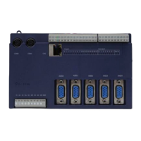
Universal controller TCI-W13-U-H/TCI-W23-U-H
Universal controller TCI-W13-U-H/TCI-W23-U-H
Universal controller TCI-W13-U-H/TCI-W23-U-H
Doc: 70-00-0384A V1.0 20160523 © Vector Controls GmbH, Switzerland Subject to alterations
Control parameters (password 241)
Warning! Only experts should change these settings! The parameters are grouped according to
control modules. After completing the logging in, a control module must be selected before
accessing the parameters.
Input configuration: 1T, 1H, 1U, 2T
Analog output configuration, AO1, AO2
Binary output configuration, do1
Internal input configuration (TI1)
Sensor sampling rate(control speed decrease as rate
increases)
Alarm 1 low limit (1T), alarm 3 low limit (1H)
Alarm 1/3 low limit values
Alarm 2high limit (1T), alarm 4high limit (1H)
Alarm 2/4 high limit values
Hysteresis alarm 1, 2, 3, 4
Calculate a range of inputs (0= not active):
1= average, 2= minimum, 3= maximum
Internal input configuration (HI1)
Sensor sampling rate(control speed decrease as rate
increases)
Alarm 1 low limit (1T), alarm 3 low limit (1H)
Alarm 1/3 low limit values
Alarm 2high limit (1T), alarm 4high limit (1H)
Alarm 2/4 high limit values
Hysteresis alarm 1, 2, 3, 4
Calculate a range of inputs (0= not active):
1= average, 2= minimum, 3= maximum
External input configuration (UI1, TI2)
Signal type (0= not active):
1= 0...10V or 0...20mA or open contact, 2= 2...10 V or
4…20 mA, 3= NTC temperature sensor
Analog input display range:
0= x0.1, 1= x1, 2= x10, 3 = x100
Analog input unit of measure:
0= no unit, 1= %, 2= °C /°F, 3= Pa
Sensor sampling rate
(control speed decrease as rate increases)
Alarm 5 low limit (1u), alarm 7 low limit (2t)
Alarm 5 low limit value (1u), alarm 7 low limit value (2t)
Alarm 6 high limit (1u), alarm 8 high limit (2t)
Alarm 6 high limit value 1u), alarm 8 high limit value (2t)
Hysteresis alarm 5 and 6 (1u), alarms 7 and 8 (2t)
Calculate a range of inputs (0=not active):
1= average, 2= minimum, 3= maximum, 4= differential
LP: Control parameters (1L)
Select loop control input (0= loop disabled):
1= 1T, 2= 1H, 3= 1U, 4= 2T
Minimum set point limit heating
Maximum set point limit heating
Minimum set point limit cooling
Maximum set point limit cooling
Enable set point compensation (0= disabled)
1= winter compensation, 2= summer compensation, 3= winter
and summer
Loop input special (0= normal):
1= combine loop 1 and loop 2
2= cascade with reverse sequence of primary loop
3= cascade with direct sequence primary loop
4= cascade with both reverse and direct sequence of
primary loop
Economy mode set point shift: (Function depends on 1L25)
The comfort (occupied) set point is shifted by the value set with
parameter. Reduces the heating set point and increases the
cooling set point.
Dead zone between heating and cooling set points
The dead zone span lies between the heating and the cooling set
point. The output is off while the measured value is within the
dead zone span. A negative dead zone is not possible.
Offset for heating PI sequence
Offset for cooling PI sequence
Integral gain heating (0.1 steps)
low= slow reaction, high= fast reaction
Integral gain cooling (0.1 steps)
Measuring interval integral (seconds)
low= fast reaction, high value= slow reaction
Action of stages:
0= cumulative: stage 1 stays on when 2 on comes on
1= single: stage 1 turns off when 2 on comes on
2= digital: stage 1 only, stage 2 only, then stage 1 plus 2
Offset for heating/reverse binary sequences
Offset for cooling/direct binary sequences
Activation of reverse/direct (heat/cool) sequence
OFF= activates based on demand
ON = follows heat/cool state of controller
Delay for heat /cool changeover when L23=OFF
Fixed set point in standby mode
OFF = Standby set point shift applies
ON = In standby mode use minimum set point limit as set point in
heating mode or maximum set point limit in cooling mode
Set point compensation range, the maximum range the set point
is shifted.
0 = Temperature setback: the set point is shifted towards set point
limit
LP: Control parameters (2L)
Select loop control input (0= loop disabled):
1= 1T, 2= 1H, 3= 1U, 4= 2T
Minimum set point limit heating
Maximum set point limit heating
Minimum set point limit cooling
Maximum set point limit cooling
Enable set point compensation (0= disabled)
1= winter compensation, 2= summer compensation, 3= winter
and summer
Loop input special (0= normal):
1= combine loop 1 and loop 2
2= cascade with reverse sequence of primary loop
3= cascade with direct sequence primary loop
4= cascade with both reverse and direct sequence of
primary loop
Economy mode set point shift: (Function depends on 2L25)
The comfort (occupied) set point is shifted by the value set with
parameter. Reduces the heating set point and increases the
cooling set point.
Dead zone between heating and cooling set points
The dead zone span lies between the heating and the cooling set
point. The output is off while the measured value is within the
dead zone span. A negative dead zone is not possible.
Offset for heating PI sequence
Offset for cooling PI sequence
Integral gain heating (0.1 steps)
low= slow reaction, high= fast reaction
Integral gain cooling (0.1 steps)
Measuring interval integral (seconds)
low= fast reaction, high value= slow reaction
Action of stages:
0= cumulative: stage 1 stays on when 2 on comes on
1= single: stage 1 turns off when 2 on comes on
2= digital: stage 1 only, stage 2 only, then stage 1 plus 2
Offset for heating/reverse binary sequences
Offset for cooling/direct binary sequences
Activation of reverse/direct (heat/cool) sequence
OFF= activates based on demand
ON = follows heat/cool state of controller
Delay for heat /cool changeover when L23=OFF
Fixed set point in standby mode
OFF = Standby set point shift applies
ON = In standby mode use minimum set point limit as set point
in heating mode or maximum set point limit in cooling mode
Set point compensation range, the maximum range the set point
is shifted.
0 = Temperature setback: the set point is shifted towards
set point limit
 Loading...