Universal controller TCI-W13-U-H/TCI-W23-U-H
Universal controller TCI-W13-U-H/TCI-W23-U-H
Universal controller TCI-W13-U-H/TCI-W23-U-H
Doc: 70-00-0384A V1.0 20160523 © Vector Controls GmbH, Switzerland Subject to alterations
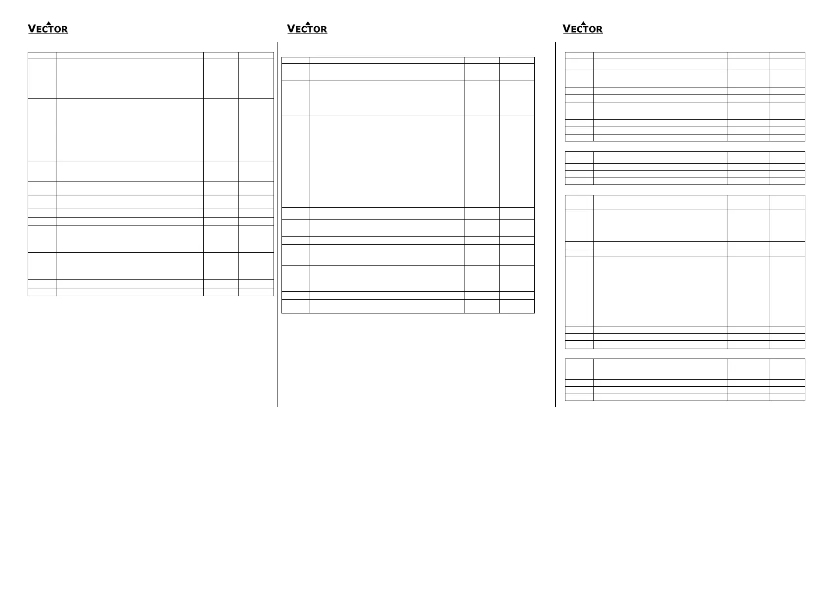
Analog output (1A, 2A)
Select control loop or special function (0= OFF):
1= LP1,
2= LP2
3= Dehumidify (4 pipe, max LP1 cooling, LP2 direct)
4= Manual positioning or time schedule controlled
(0…100%)
5= Transmit value of an input
When 1A00=1 configure output:
0= Heating/reverse
1= Cooling/direct
2= Heating and cooling (2 pipe)
3= Transmit set point
When 1A00 = 4 manual positioning or time schedule controlled
0 = Time schedule controlled only
1 = Manual positioning and time schedule controlled
When 1A00=5, select input (0= function disabled):
1= 1T, 2= 1H, 3= 1U, 4= 2T
Type of output signal: OFF= 0...10V, 0...20mA, ON= 2...10V,
4...20mA
Minimum limitation of output signal default and in loop heating
mode
Maximum limitation of output signal default and in loop heating
mode
Minimum limitation of output signal in loop cooling mode
Maximum limitation of output signal in loop cooling mode
Choose alarm to set output to 100% (output 0% on conflicting
alarms)
Alarm: 1 2 3 4 5 6 7 8
Choose alarm to set output to 0%. (output 0% on conflicting
alarms)
Alarm: 1 2 3 4 5 6 7 8
Transmit value (1A00=5): minimum input value
Transmit value (1A00=5): maximum input value
Binary output – binary control
Enable digital or PWM output
OFF= 1d is a digital output
ON = 1d is a PWM output
Select control loop or special function (0= OFF)
1= LP1
2= LP2
3= Dehumidify (4 pipe, max LP1 cooling, LP2 direct)
4= Manual positioning (on/off)
5= State functions
When 1d01=1, configure output:
0= Stage 1 heating/reverse
1= Stage 1 cooling/direct
2= Stage 1 heating and cooling, reverse and direct
3= Stage 2 heating/reverse
4= Stage 2 cooling/direct
5= Stage 2 heating and cooling, reverse and direct
If 1d01 = 4 Manual positioning or time schedule controlled
0 = Time schedule controlled only
1 = Manual positioning and time schedule controlled
When 1d01=5, select state functions:
0= ON if controller operation state is ON
1= ON while demand on any output
2= ON while controller in heating mode and
operation state ON
3= ON while controller in cooling mode and operation state ON
Switch-off delay (time output active with no more demand)
Delay is in seconds or minutes depending on d09
Switch-on delay (time demand active before output on)
In state mode 1d01=5 outputs disabled during switch-on delay
Delay is in seconds or minutes depending on d09
Activate PWM, set cycle time, seconds (>0 activates, 0 deactivates)
Choose alarm to set output to ON (output OFF on conflicting alarms)
Alarm: 1 2 3 4 5 6 7 8
Choose alarm to set output to OFF (output OFF on conflicting
alarms)
Alarm: 1 2 3 4 5 6 7 8
Display fan symbol while active
Binary switching delays in minutes or seconds
OFF = delays are in seconds, ON = delays are in minutes
Special functions – SP compensation
Select compensation input (0= function disabled):
1= 1T, 2= 1H, 3= 1U, 4= 2T
Winter compensation set point setback
OFF= shift toward control loop heating set point minimum
ON= shift toward control loop heating set point maximum
Winter compensation lower limit value – end shift
Winter compensation upper limit value – start shift
Summer compensation se tpoint setback
OFF= shift toward control loop cooling set point minimum
ON= shift toward control loop cooling set point maximum
Summer compensation lower limit value – start shift
Summer compensation upper limit value – end shift
Show hot/cool symbol while compensation active
Special functions – remote control comfort – economy
Select comfort/economy changeover input (0= disabled):
1= 1T, 2= 1H, 3= 1U, 4= 2T
Economy activation delay (seconds)
Special functions – remote control enable – disable
Select enable–disable input (0=function disabled):
1= 1T, 2= 1H, 3= 1U, 4= 2T
Manual override permitted (without waiting for delay).
This function allows starting the controller; although the
enable conditions are not met. The controller will switch off
again if the running conditions are not met until the disable
delay is expired.
Range of limits:
OFF = When limit 2 is greater than limit 1, enable when
input value is greater than limit 2,disable when input
value is less than limit 1.
When limit 2 is less than limit 1, enable when input
value less than limit 1, disable when input value is
greater than limit 2.
ON = When limit 2 is greater than limit 1enable when input
value is between limit 1 and limit 2.
When limit 2 is less than limit 1, enable when input
value below limit 2 or above limit 1
Disable in case of alarms
Special functions – remote heat / cool (reverse / direct) change
Select heat/cool changeover input (0=function disabled):
1= 1T, 2= 1H, 3= 1U, 4= 2T,
5= h/c status loop 1, 6= h/c status loop 2
Cooling activation delay (seconds)
 Loading...