TCI-W13, TCI-W23 Universal Controller
CONTROL LOOP CONFIGURATION
Doc: 70-00-0365A, V1.5, 20230901 © Vector Controls GmbH, Switzerland Page 12-18
Subject to alteration
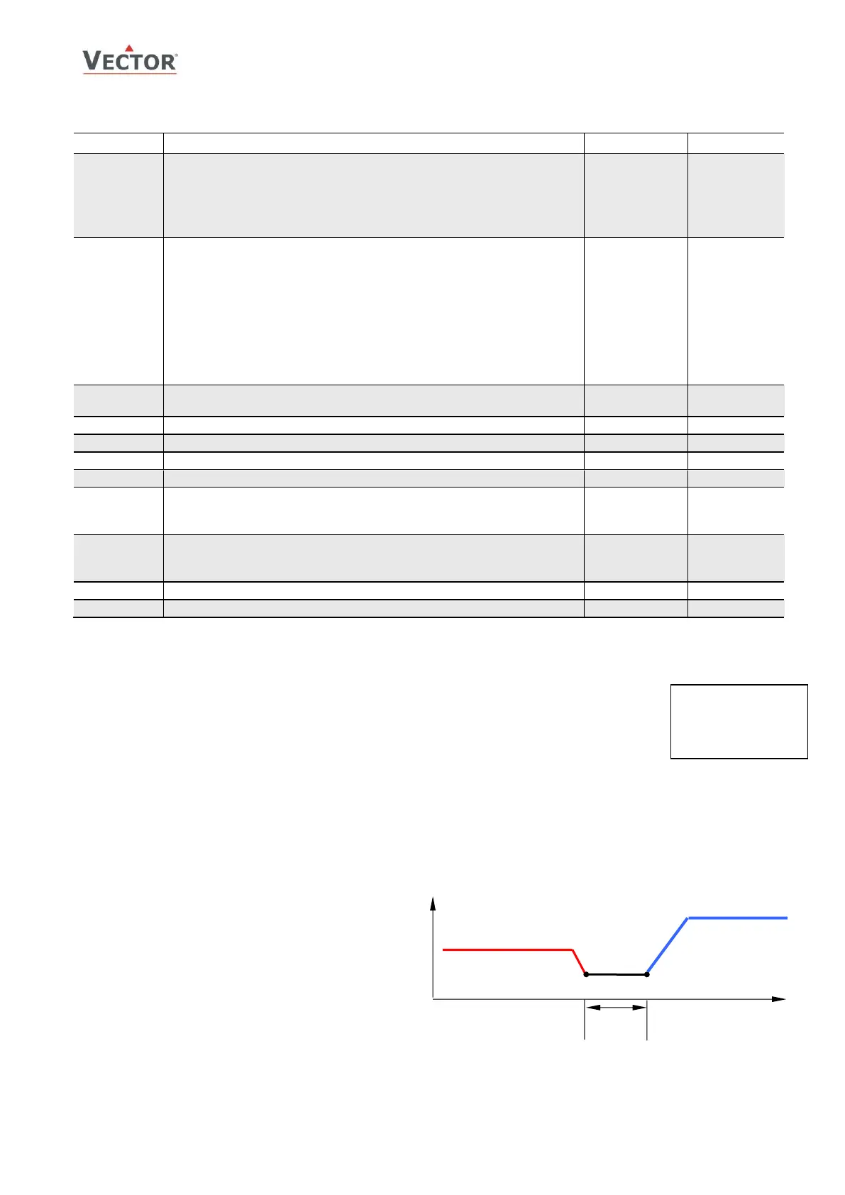
Legend
T, U Input signal
O
SH
Offset heating/direct
O
SC
Offset cooling/reverse
X
DZ
Dead zone
X
SBY
Economy set point shift
W
H
Set point heating/reverse
W
C
Set point cooling/direct
Q
C
, Q
D
Binary sequences cooling/direct
Q
H
, Q
R
Binary sequences heating/reverse
Action of stages:
0 = cumulative: stage 1 stays on when 2 on comes on
1 = single: stage 1 turns off when 2 on comes on
2 = digital: stage 1 only, stage 2 only, then stage 1 plus 2
Offset for heating/reverse binary sequences
Offset for cooling/direct binary sequences
Activation of reverse/direct (heat/cool) sequence
OFF = activates based on demand
ON = follows heat/cool state of controller: Set manually or by
auxiliary function (FU20...FU23)
Delay for heat /cool changeover when L23=OFF
➔ Cumulative stage action (L16 = 0) is typically used in electric heat applications, and single stage action (L16 = 1) in
fan speed applications. Digital stage action (L16 = 2) is especially useful in electric heat applications to generate
three steps with just two outputs. For example: Step 1 = 100W, step 2 = 200W, step 3 = 300W.
➔ Switching hysteresis (L21) is the difference between switching on and switching off. A small hysteresis will increase
the number of switching cycles and thus the wear on associated equipment.
➔ With switching delay (L22) cumulative stages will not switch on simultaneously. With a sudden demand or initial
power stage 2 will not start earlier than 10 seconds (default value) after stage 1 has been initiated.