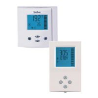
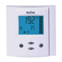
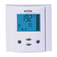
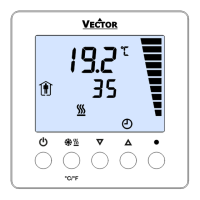
TCY3-T1102 Engineering Manual
Doc: 70-000003 V1.0, 20150710 © Vector Controls GmbH, Switzerland Page 15
Subject to alteration
Configuration of controller
Proceed in the following steps in order to adapt the controller to its application:
1. Set jumpers for inputs and outputs
2. Connect power supply and inputs
3. Set user settings (UP)
4. Program input parameters (IP)
5. Program control parameters (1L or 2L)
6. Program output parameters (OP)
7. Test function of unit
8. Switch off power
9. Connect outputs & test control loop
Configuration parameters for firmware version 3.1
The TCY3-T1102 can be adapted to a wide variety of applications. The adaptation is done through parameters. The
parameters can be changed on the unit without the need of additional equipment.
Identifying the firmware version
The parameters and functionality of controller depend on its firmware version and revision. It is therefore important to use
a matching product version and parameter set. The firmware version and revision version can be found when pressing
simultaneously the and keys during several seconds. On the upper 7 segment display, the firmware version can be
found, on the lower 7 segment display the current revision index (or “sub-version”).
Control parameters (password 241)
Warning! Only experts should change these settings! The parameters are grouped according to control modules. After
completing the logging in, a control module must be selected before accessing the parameters. See user parameters for
login procedure.
Loop 1: heat/cool: temperature input 1
Loop 2: universal: analog input
Control parameters temperature input (loop 1)
Minimum set point limit for heating
Maximum set point limit for heating
Minimum set point limit for cooling
Maximum set point limit for cooling
Dead zone between heating & cooling set point X
DZ
Cascade control: set point provided by primary loop (loop 2),
loop 1 is secondary loop)
0 = no cascade control
1 = cascade control with loop 2 on heating only
2 = cascade control with loop 2 on cooling only
3 = cascade control with loop 2 heating and cooling
Summer – winter compensation
0 = disabled
1 = winter compensation only
2 = summer compensation only
3 = winter and summer compensation
Automatic change of heat / cool setting by demand
OFF = manual (2-pipe)
ON = automatic (4-pipe)
 Loading...
