Testing Procedures Simulated Leak Test - 4 Step Test
8
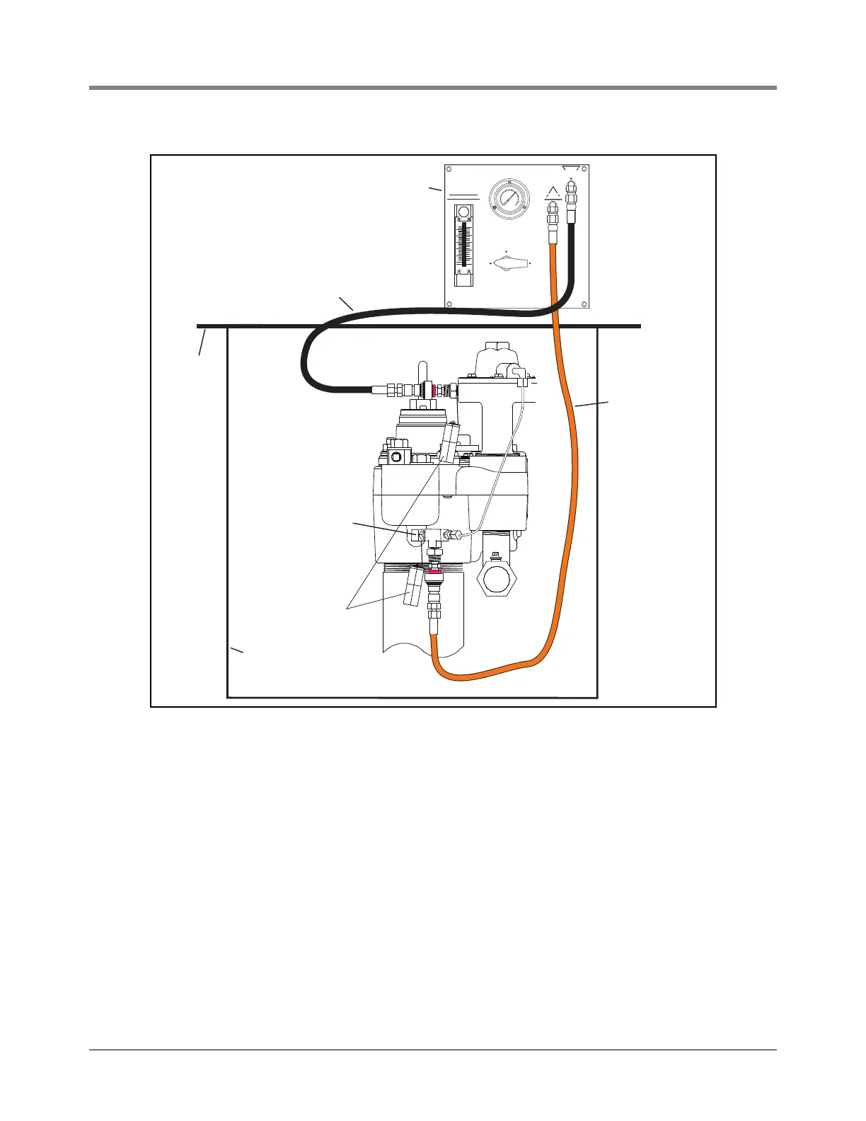
Figure 3. Example FX tester connection to the Red Jacket pump
The FXT will be required for this procedure. The V-R FX2 Series LLD and the Snap Tap Connectors must be
installed before testing can begin. Refer to FX installation instructions 042-106-1.
1.
a. Connect the black hose of the FXT to the Snap Tap Connector at the tank test port of the pump. The black
hose is the path to the tank. Line pressure can be relieved through this path.
b. Connect the orange hose of the FXT to the Snap Tap Connector on the FX2 Series LLD. The orange hose
is the path to the line.
c. Turn FXT’s Selector Valve to ‘Pump/Line Pressure’ position as shown in Figure 4. When the selector valve
is in this position, the FXT is monitoring actual line pressure. As actual line pressure is displayed on the
compound gauge, specifications can be checked.
d. Observe pump operating pressure. This step may be done while dispensing is in progress. Check pump
operation specifications to verify pump pressure output and relief pressure.
e. From Table 1, below, select a leak rate at which to test. The top row of numbers (starting with 3) are the
choices, reflected in gph.
LINE
PRESSURE
3
0
3
0
2
0
20
1
0
1
0
1
0
0
4
0
5
0
6
0
VENT
LEAK
TEST
PRESSURE
RELIEF
SELECTOR VALVE
PUMP/LINE
PRESSURE
LEAK RATE
FLOW METER
VALVE
DO NOT OVER
TIGHTEN VALVE
GPH
25
20
15
10
10
15
20
5
1
00
1
5
GPH
G
A
S
O
L
I
N
E
D
I
E
S
E
L
FX Tester
Grade
Sump
Black Hose
Orange Hose
Tethered
Cap
(Shown) FX2V
FX2DV
272-2.eps
1/4” NPT 45 degree
elbow and tee install
in tank vent port