Installation Guide Mag Sump Sensor Installations - STP Sump
19
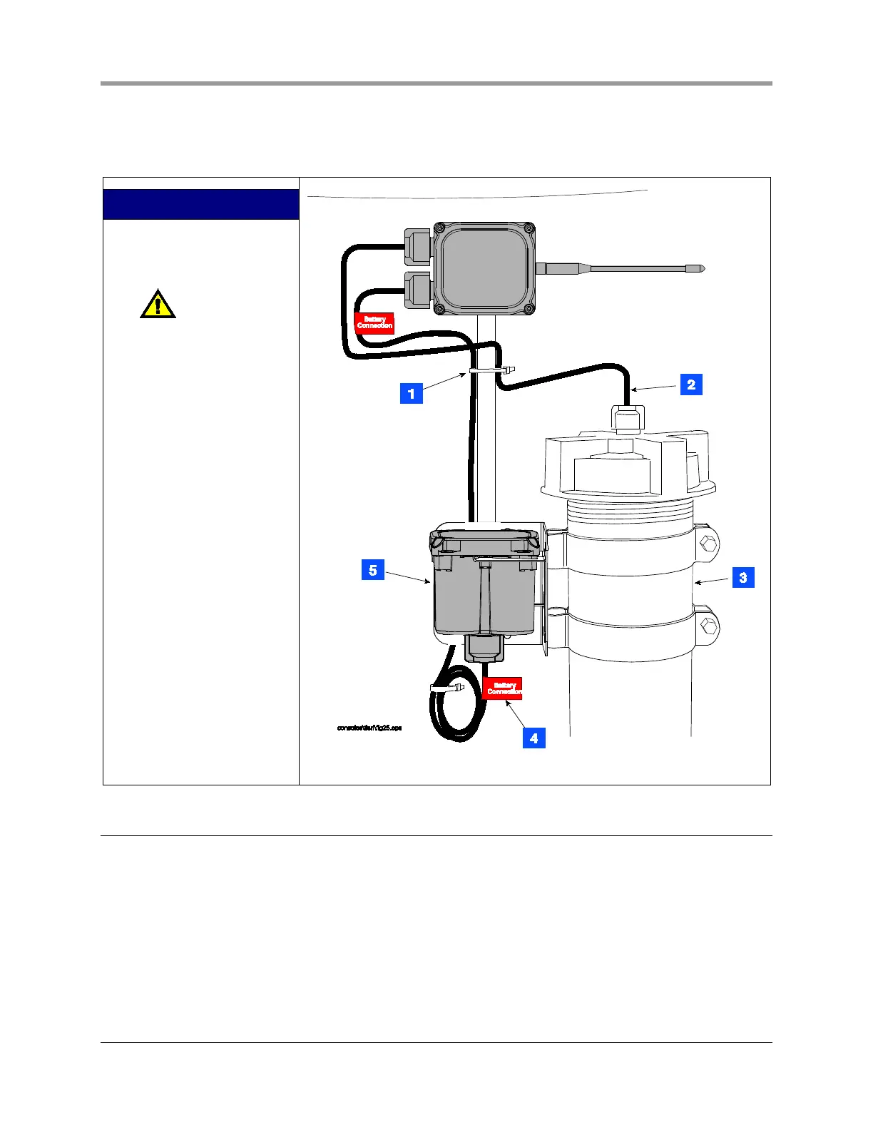
7. Insert the battery pack into the battery support bracket as shown in Figure 18.
8. Attach power/probe cables as described in the section below entitled “Connecting cables to the
Transmitter”.
LEGEND FOR NUMBERED
BOXES IN FIGURE 18
1. Tie wrap cables
2. Probe cable
NOTE: Intrinsically
safe wiring shall be
installed in accordance with
Article 504-20 of the NEC,
ANSI/NFPA 70.
3. Probe Riser
4. Red battery ID labels - 2
places
5. Battery pack - insert into
support bracket
Figure 18. Mag Probe Installation Example (in operational configuration)
Mag Sump Sensor Installations - STP Sump
A transmitter/battery pack pair can be installed with a Veeder-Root Mag Sump sensor within the STP sump.
The transmitter /battery pack installs similar to the way it installs in probe sumps. The exception is that the
support brackets will attach to the pump’s 2-inch discharge piping rather than to the STP’s 4-inch riser as
shown in Figure 18.
Install the Mag Sump sensor using the included universal sensor mounting kit and following the instructions
included with the sensor.
Once the sensor/battery pack is installed, attach power/sensor cables as described in the section below
entitled “Connecting cables to the Transmitter”.
 Loading...